Team:ETH Zurich/Modeling/SingleCell
From 2011.igem.org
Brief overview of the model
The model of our system consists of two connected parts: the band detector and the toggle switch. The band detector produces green fluorescent protein upon a detection of a certain range (band) of acetaldehyde concentration. After acetaldehyde concentration passes a certain threshold the toggle switch turns the system red (red fluorescent protein is expressed).
Acetaldehyde from the smoke binds to AlcR and the formed complex then inhibits TetR. TetR inhibits LacI and CI. CI also inhibits LacI which inhibits GFP. This part of the circuit makes up the band detector. The Acetaldehyde-AlcR complex is considered as constant input to our system. By simulating with varying acetaldehyde concentrations we can see at which concentration is the band , i.e. at which concentrations GFP is produced. The connection to the switch is the LuxI inbition by CI. LuxI in turn produces AHL, which is described in our model as two states (AHL external and AHL internal). AHL diffuses in and out of the cell and after binding of AHL internal to LuxR, the complex R is created. In the model the LuxR concentration is taken as a parameter since it does not vary with time. Finally, RFP is inhibited by the complex R.
Our model has 9 states in total and 37 parameters, including the Acetaldehyde-AlcR input and LuxR. Basal expression is considered for none of the states and linear degradation is considered for all of them.
Band Detector
The band detector is an amplitude band-pass filter that gives a GFP output when acetaldehyde is in a certain concentration range. The filter is a feed-forward system with 2 branches – an amplitude low-pass filter and an amplitude high-pass filter – interconnected by a NOR gate.
The input of the system is acetaldehyde which binds to AlcR. After the complex TetR inhibition by the acetaldehyde-AlcR complex the systems splits into the 2 branches, the slow branch and the fast branch.
The fast branch is the amplitude low-pass filter. This means that it will repress the production of GFP when the acetaldehyde concentration goes above the high threshold.In other words, GFP is produced only at low acetaldehyde concentrations. High acetaldehyde concentration will repress TetR which will not be able to repress LacIm1, GFP production being thus inhibited.
The slow branch is the amplitude high-pass filter which represses GFP when acetaldehyde concentration falls below the low threshold or in other words GFP is produced only at high levels of acetaldehyde.
By combining these 2 filters, GFP is produced when neither LacIm1 or LacI represses it, which is region between the two thresholds. This region is the range of acetaldehyde concentration which can trigger the GFP pulse. The ODEs for the species involved in the band detector are given below.
We simulated the model for 5000s and for various concentrations of acetaldehyde. In the following figure you can see how the steady state concentration of GFP changes for different input concentrations of acetaldehyde. The band is formed when the acetaldehyde concentration is approximately in the range of 500-1500 microMolars.
The peak of the GFP pulse is observed when the acetaldehyde concentration is 1000 microMolars. The time course for GFP for the corresponding acetaldehyde concentration can be seen in the following figure.
FIGURE NEEDED !!!
Toggle Switch
NEED TO THINK WHAT TO WRITE !!!
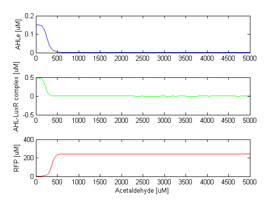
At high acetaldehyde concentrations, TetR is repressed, so the repression of CI by TetR can not be established. CI is expressed and it inhibits the production of LuxI, which means that AHL is not produced. Once AHL is not there, it can not bind to LuxR, so LuxR can't repress RFP any more. This results of RFP expression, the system is "switched to red". We can also say that this module of the model acts as a low pass amplitude filter for AHL, or high pass amplitude filter for acetaldehyde, since AHL is produced only when the acetaldehyde levels are low.
The ODEs for the states involved in the second module of the system are given below:
The RFP steady state concentration plotted against increasing acetaldehyde concentration is presented below. One can clearly see the switch. The RFP appears after acetaldehyde crosses the threshold of microMolars.
TO INSERT
 "
"


