Team:Paris Bettencourt/Experiments/T7 diffusion
From 2011.igem.org
| (40 intermediate revisions not shown) | |||
| Line 12: | Line 12: | ||
<li>We characterized the pT7 promoter in <i>E.coli</i></li> | <li>We characterized the pT7 promoter in <i>E.coli</i></li> | ||
<li>We characterized the so-called T7 autoloop (receiver) both in <i>E.coli</i> and <i>B.subtilis</i></li> | <li>We characterized the so-called T7 autoloop (receiver) both in <i>E.coli</i> and <i>B.subtilis</i></li> | ||
| + | <li>We saw that our constructs behave accordingly to the <a href="https://2011.igem.org/Team:Paris_Bettencourt/Modeling/T7_diffusion">model</a> we made, except for the T7 autoloop leakage which we expected to be higher than in the model anyway</li> | ||
</ul></p></b></div> | </ul></p></b></div> | ||
<h2>Design overview</h2> | <h2>Design overview</h2> | ||
| Line 94: | Line 95: | ||
<html> | <html> | ||
<h2>Characterization of the T7 signal amplification leakage</h2> | <h2>Characterization of the T7 signal amplification leakage</h2> | ||
| - | <img src="https://static.igem.org/mediawiki/2011/d/dc/Autoloop_pHM3_2d.png"/> | + | <center> |
| - | <img src="https://static.igem.org/mediawiki/2011/5/59/Autoloop_chromosome2d.png" /> | + | <table> |
| - | <img src="https://static.igem.org/mediawiki/2011/1/1b/Pos%2B_ctrl_3610.png" /> | + | <tr> |
| - | <img src="https://static.igem.org/mediawiki/2011/a/a1/Neg_ctrl_expo_RFP.png" /> | + | <td> |
| + | <img src="https://static.igem.org/mediawiki/2011/d/dc/Autoloop_pHM3_2d.png"/></td> | ||
| + | <td><img src="https://static.igem.org/mediawiki/2011/5/59/Autoloop_chromosome2d.png" /></td> | ||
| + | </tr> | ||
| + | <tr> | ||
| + | <td> | ||
| + | T7 autoloop in pHM3 | ||
| + | </td> | ||
| + | <td> | ||
| + | T7 autloop in chromosome | ||
| + | </td> | ||
| + | </tr> | ||
| + | <tr> | ||
| + | <td><img src="https://static.igem.org/mediawiki/2011/1/1b/Pos%2B_ctrl_3610.png" /> | ||
| + | </td> | ||
| + | <td><img src="https://static.igem.org/mediawiki/2011/a/a1/Neg_ctrl_expo_RFP.png" /> | ||
| + | </td> | ||
| + | </tr> | ||
| + | <tr> | ||
| + | <td> | ||
| + | Positive control | ||
| + | </td> | ||
| + | <td> | ||
| + | negative control | ||
| + | </td> | ||
| + | </tr> | ||
| + | </table> | ||
| + | </center> | ||
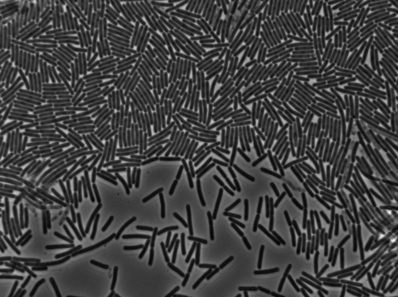
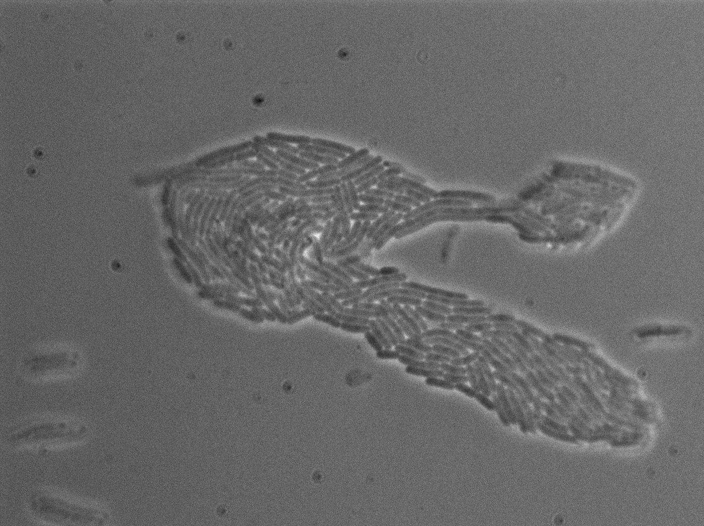
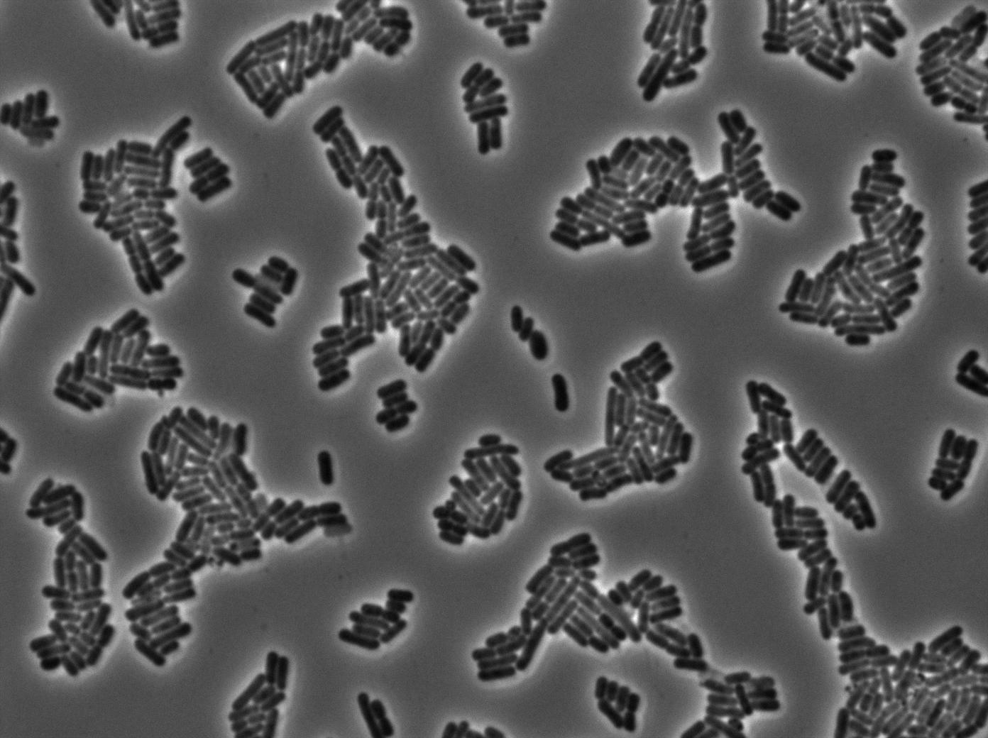
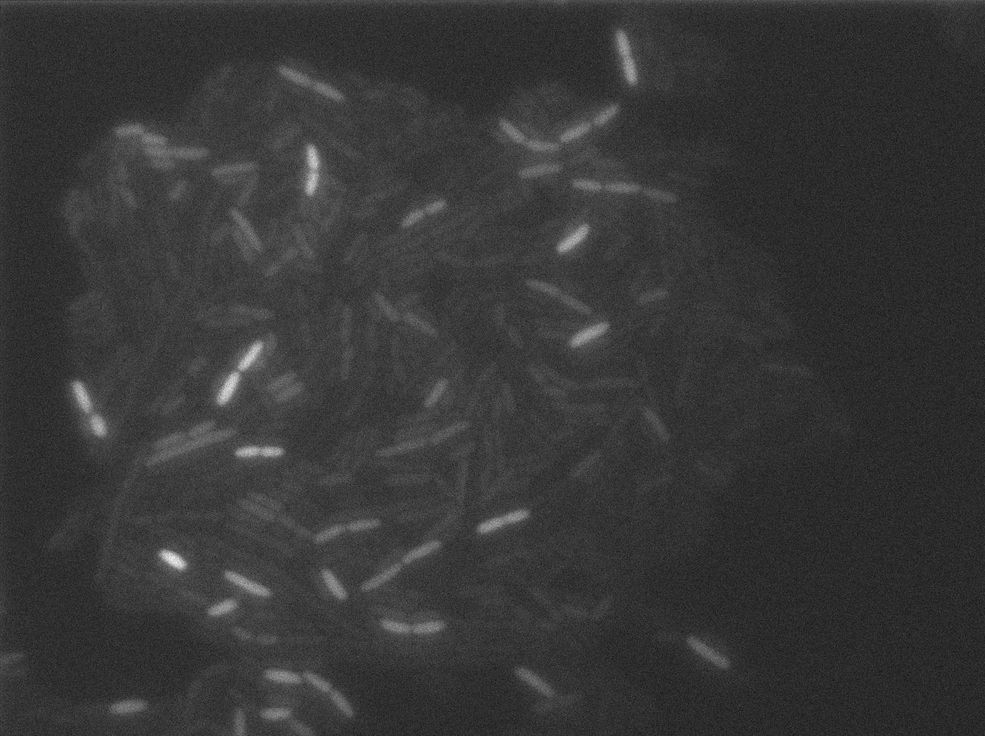
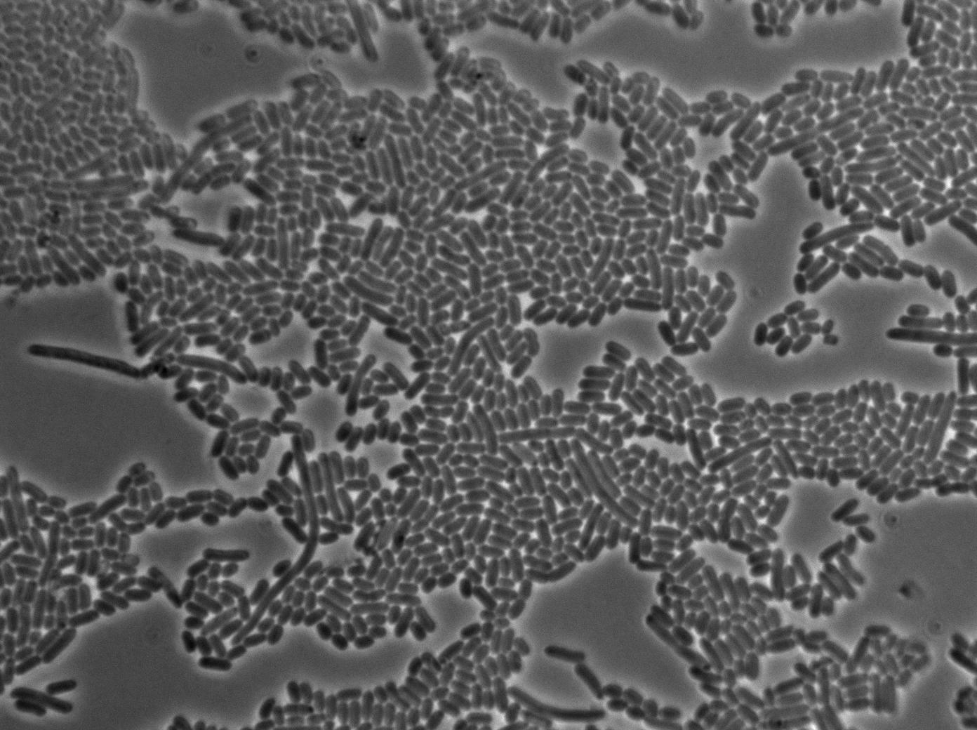
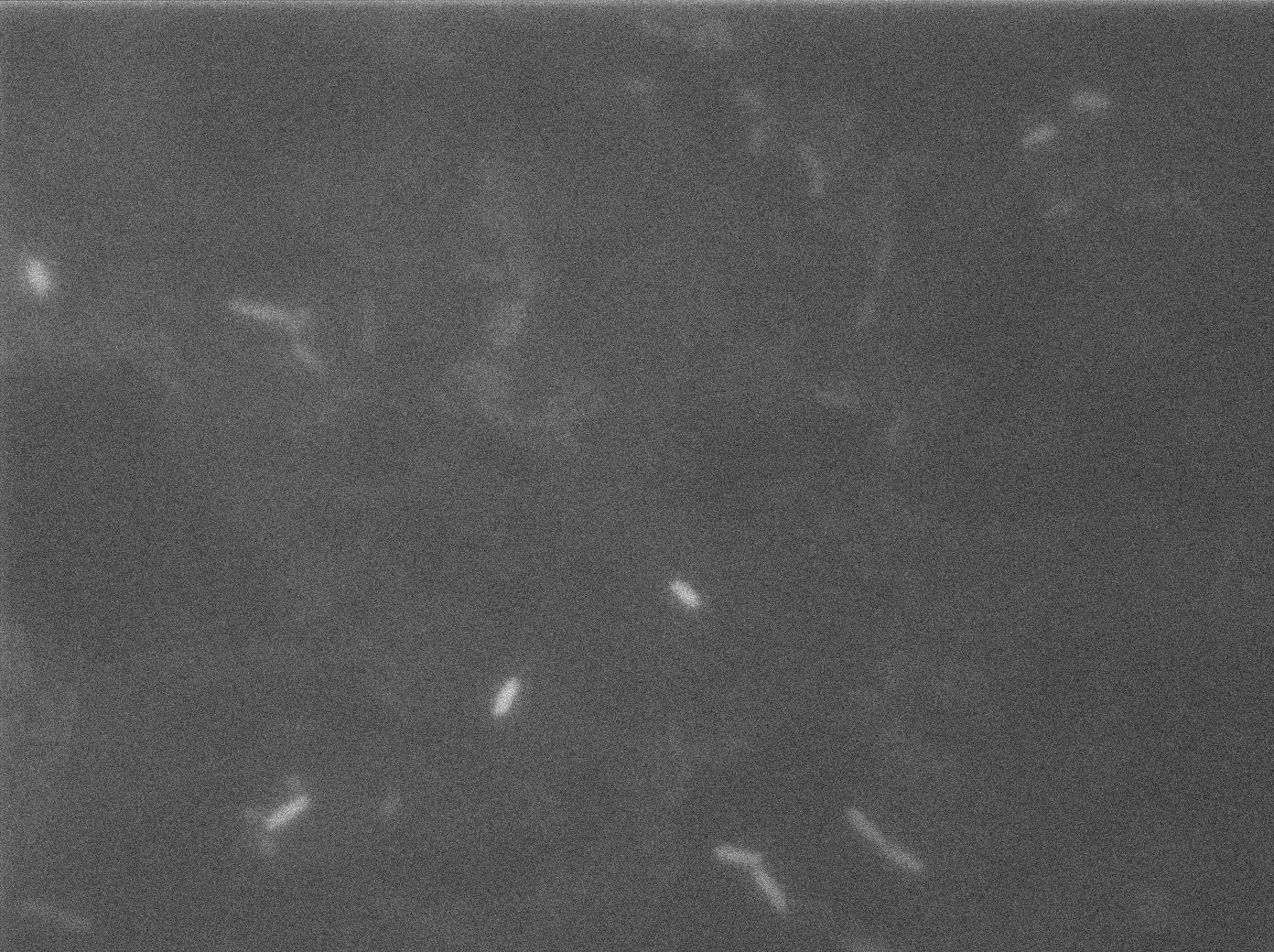
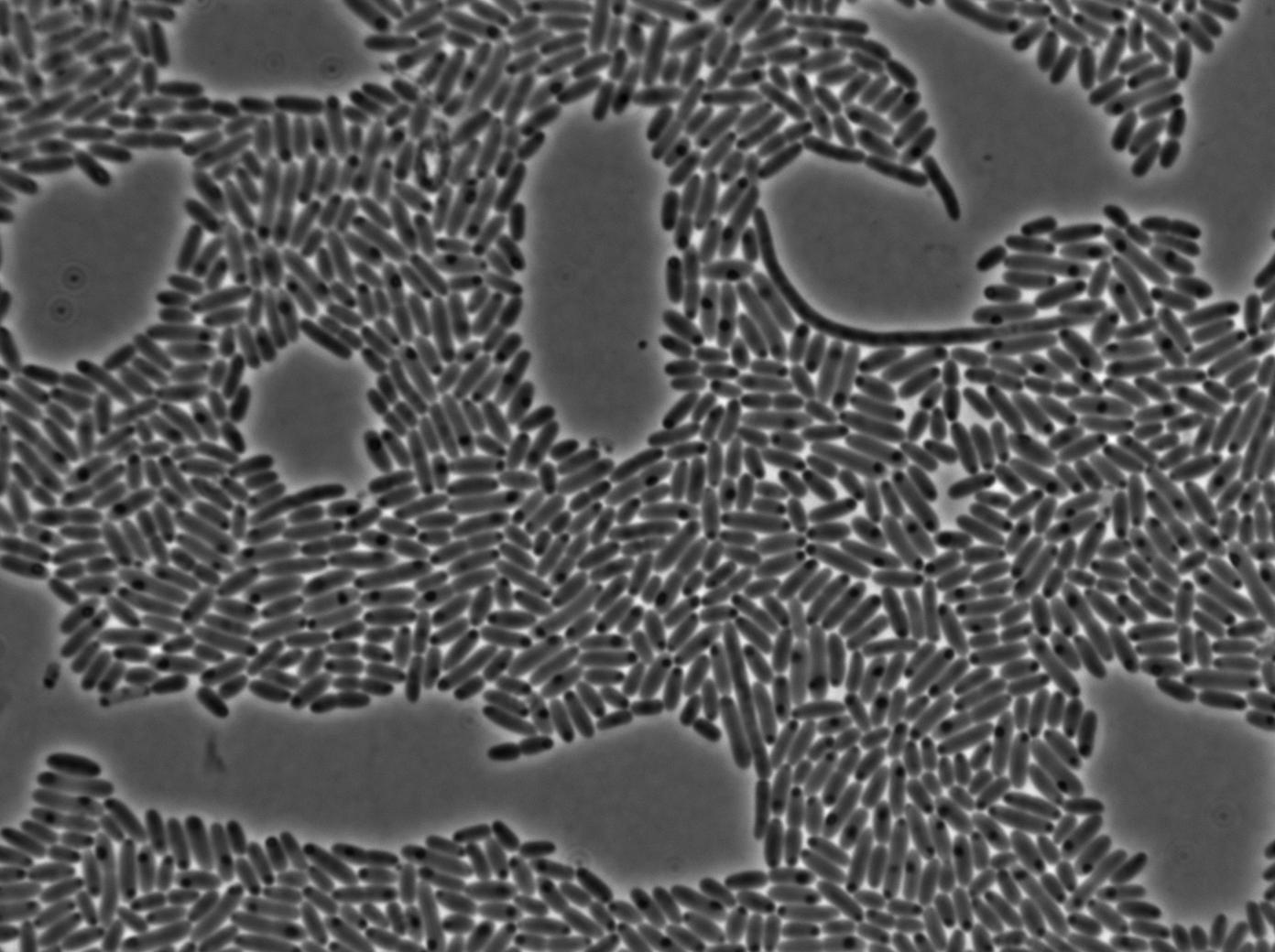
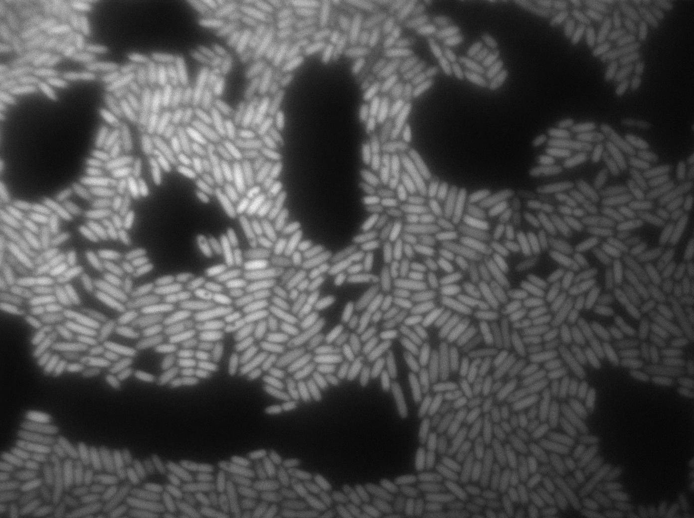
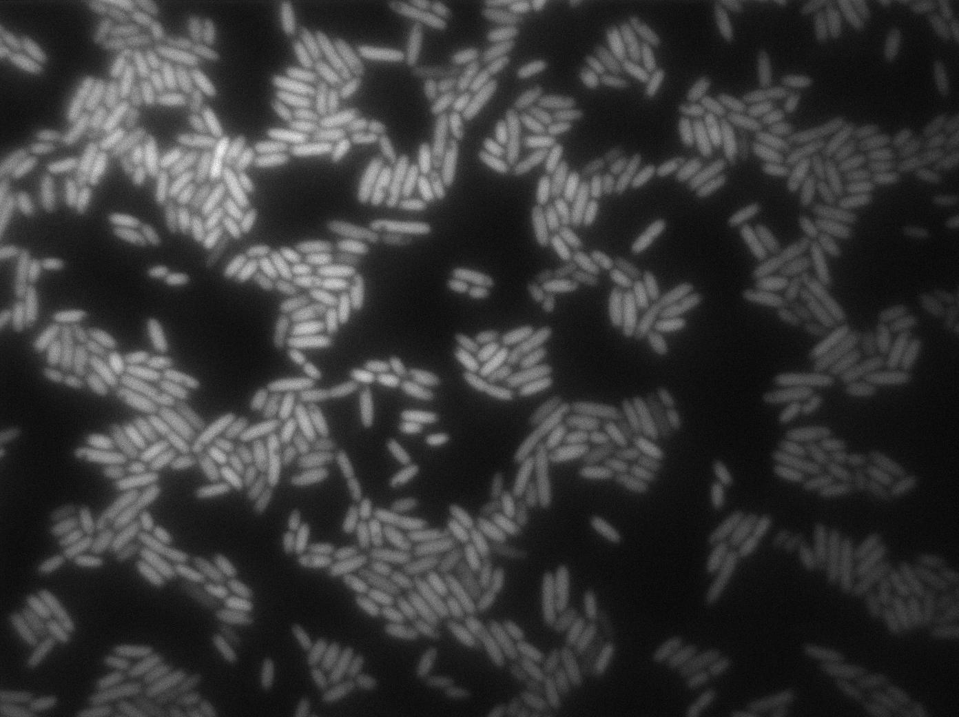
| + | The T7 autoloop cloned inside the vector pHM3 show strong leakage. In consequence almost all the cells seems to be on the ON state (expressing GFP). In contrast the same contruct integrated inside the chromosome in the AmyE locus show no leakage at all, giving us a good background condition where the activation of the autoloop by T7 polymerase from a receiver cell can be easily detected. | ||
<p>We characterized T7 autoloop (receiver part of the construct, <a href="http://partsregistry.org/wiki/index.php/Part:BBa_K606036">BBa_K606036</a>) in E.coli, when hosted in the plasmid pSB1C3.</p> | <p>We characterized T7 autoloop (receiver part of the construct, <a href="http://partsregistry.org/wiki/index.php/Part:BBa_K606036">BBa_K606036</a>) in E.coli, when hosted in the plasmid pSB1C3.</p> | ||
<p>We know that, due to stochastic leakage, some cells should express T7 RNA polymerase even without induction. Our <a href="https://2011.igem.org/Team:Paris_Bettencourt/Modeling/T7_diffusion">modeling</a> suggests that only a few polymerases are required to activate the T7 autoloop. Without any induction, we therefore <em>expected to have a few very bight cells</em> (autoloop activated) while the other remain dark or only marginally fluorescent (bit of leakage on the GFP gene only).</p> | <p>We know that, due to stochastic leakage, some cells should express T7 RNA polymerase even without induction. Our <a href="https://2011.igem.org/Team:Paris_Bettencourt/Modeling/T7_diffusion">modeling</a> suggests that only a few polymerases are required to activate the T7 autoloop. Without any induction, we therefore <em>expected to have a few very bight cells</em> (autoloop activated) while the other remain dark or only marginally fluorescent (bit of leakage on the GFP gene only).</p> | ||
| Line 228: | Line 257: | ||
</tr> | </tr> | ||
</table> | </table> | ||
| - | |||
| - | |||
Latest revision as of 03:42, 29 October 2011

Building and characterizing the T7 RNA polymerase design
The T7 RNA polymerase diffusion design was the first one we thought of. It uses the RNA polymerase of the T7 phage, giving us perfect orthogonality to B.subtilis genome. We use an auto-amplification device base on this polymerase that we call T7 autoloop. This autoloop is also used in the tRNA amber diffusion design. We successfully BioBricked and characterized all our constructs for this design and made them available for the synthetic biology community. Our results are detailed below.
Abstract
Results for the T7 RNA polymerase diffusion design:
- We successfully BioBricked both the T7 RNA polymerase emitter (BBa_K606039) and the T7 autoloop (BBa_K606036) constructs and sent them to the registry
- We integrated our construct both in E.coli and B.subtilis
- We characterized the pT7 promoter in E.coli
- We characterized the so-called T7 autoloop (receiver) both in E.coli and B.subtilis
- We saw that our constructs behave accordingly to the model we made, except for the T7 autoloop leakage which we expected to be higher than in the model anyway
Design overview

Schematic summary of the T7 diffusion device
All of the parts of the above design have been BioBricked, characterized both in E.coli and B.subtilis, and sent to the registry.
More details on the design are available here.
Diffusion experiments
Results negative at first
This design was successfully implemented both in E.coli and B.subtilis. We were therefore able to test the diffusion of the T7 RNA polymerase through nanotubes. We ran several experiments:
- Diffusion from E.coli to B.subtilis with our receptor construct on a plasmid. Find more about it here
- Diffusion from B.subtilis to B.subtilis with our receptor construct on a plasmid. Find more about it here.
- Diffusion from B.subtilis to B.subtilis with our receptor construct integrated in the genome. Find more about it here.
The first three experiments gave us negative results. We saw no obvious increase of the GFP expression in receiver cells when our construct was on a plasmid and absolutely no GFP fluorescence when it was integrated in the genome.
Unexepected breakthrough
However, our microfluidic experiment gave unexepected and encouraging results. We used for this experiment two B.subtilis strains (one emitter, one receiver, both integrated in the genome). Our chromosomic T7 autoloop was brightly activated during this experiment, but only in densely packed mix of emitter and receiver cells. Find more about this experiment here.
Seeing that cell concentration seemed to be the key factor and taking advantage of our perfectly not leaky chromosomic autoloop we conducted a final set of experiments where we concentrated our cells even more. We invite you to see our final results here.
Parts and BioBricks construction
You can find the cloning plan for the T7 RNA polymerase design below:


Setback with the pHyperspank promoter
At the beginning of the project, we intended to use a pHyperSpank promoter (Ph-s, BBa_K143055) in front of the emitter construct. The Ph-s promoter is repressed by LacI and would have allowed us to use an IPTG-inducible promoter. However, our first experiments with the promoter were inconclusive. We sequenced our sample and realized that we had received a BioBrick of the size of Ph-s but not the one we expected. It was anoter gene entirely. Rather than losing weeks of experiments waiting for another HyperSpank promoter, we chose to use a constitutive Pveg promoter (BBa_K143053).
Characterization of the T7 promoter
In order to characterize the pT7 promoter, we used the construct pT7-RBS-GFP-T7ter. This construct was transformed into BL21 strains (E.coli) expressing the T7 polymerase under IPTG induction.Fluorescence kinetics
The measurements have been carried out on a spectrophotometer at 37°C under transient shaking. The experiment lasted 4h, we tested several colonies and several IPTG concentrations. The OD at 600nm and the fluorescence of the GFP (exc: 470nm / meas:515 nm) was measured every 5 min and the ratio of the two was calculated.
All values were normalized by substracting the fluorescence/OD value of the well with 0 mM IPTG at time 0. The values given are in arbitrary units.
After 2 hrs of induction, we see a clear increase of the fluorescence proportional to the IPTG concentration (that is to say with the quantity of T7 polymerase induced in the cell). After 4 hrs, the expression of GFP under the pT7 is still not saturated
Here we plot the ratio of induction of the T7 polymerase dependant construct for the different concentrations of IPTG at a given time (4 hrs) taking the well with 0 IPTG at time 0 as the reference.
Characterization of the T7 RFP emitter
Here we highlight the RFP and T7 expression by showing the fluorescence intensity in our cells.The first pictures show that the RFP construct is working efficiently since cells are glowing with RFP fluorescence.
Characterization of the T7 signal amplification leakage
 |
 |
| T7 autoloop in pHM3 | T7 autloop in chromosome |

|

|
| Positive control | negative control |
We characterized T7 autoloop (receiver part of the construct, BBa_K606036) in E.coli, when hosted in the plasmid pSB1C3.
We know that, due to stochastic leakage, some cells should express T7 RNA polymerase even without induction. Our modeling suggests that only a few polymerases are required to activate the T7 autoloop. Without any induction, we therefore expected to have a few very bight cells (autoloop activated) while the other remain dark or only marginally fluorescent (bit of leakage on the GFP gene only).
We tried two configurations: one with a terminator before the pT7 promoter and one without. This was to see if we could reduce leakage with one extra terminator.
These pictures show that the T7 GFP autoloop system is efficient since some cells are glowing with GFP fluorescence. Thus, we can conclude that the T7 autoloop is activated because of stochastic leakage.
Finally, we notice there is no difference between the GFP autoloop with and without terminator before the T7 promoter. It could be due to that terminator which is a B.subtilis terminator. Moreover, we know that this E.coli plasmid has 4 terminators before our construct, pretty much nullifying the effect of our extra terminator in E.coli.
Testing the T7 autoloop in cells expressing T7 RNA ploymerase
To characterize quantitatively the T7 autoloop induction and memory we did two experiments whose protocols is described below.
T7 autoloop contruct : pT7_RBS_T7_RBS_GFP_t7t
Control construct : pT7_RBS_GFP_tt
ProtocolBoth constructs were transformed into the E.coli strain BL21 that expresses the T7 polymerase when induced with IPTG.
Signal amplification by the T7 autoloop system in E.coli.:After an overnight culture, the two strains were introduced into a 96-well spectrophotometry plate in the presence or absence of IPTG (0.01mM). The initial OD600 was approx. 0.2. The green fluorescence and the OD600 were measured every 5min for 4hrs.
Memory of autoloop-amplified signal over time in E.coli :The two strains were cultured overnight, then induced for two hours with IPTG (0.01mM) in falcons. A wash was then performed by centrifuging and rediluting the cells in new LB medium. The two strains were then diluted in the wells of the spectrometry plate in the presence of glucose 4% to an OD600 of approx. 0.2.The green fluorescence and the OD600 were measured every 5min for 4hrs. (The delay caused by manipulation time was taken into account in the graph.)


We put our T7 autoloop construct in in BL21 strains of E.coli, hosted in the plasmid pSB1C3. BL21 strains are E.coli cells producing T7 RNA polymerase upon IPTG induction. You can also use glucose as an inhibitor of the system.
Here we used a simple protocol to make sure that we have nice positive and negative controls for furhter experiments. What follows shows that our cells are able to keep a memory of an active state.
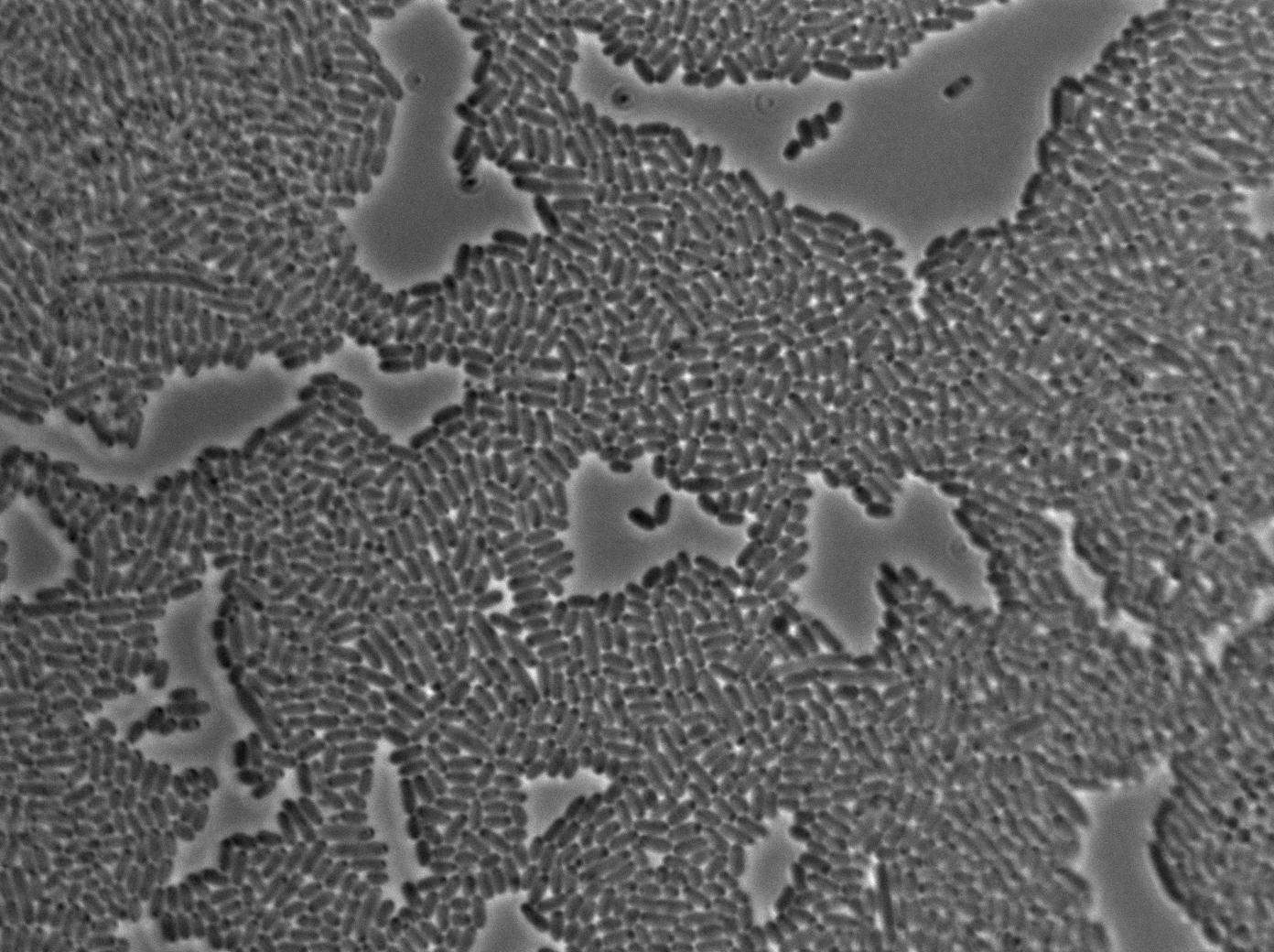
Negative Control
First we launch cells from the overnight culture tube without IPGT. Then we wash the cells and relaunch them with glucose to inhibit out gene expression.
Here we can see the minimal leak of the GFP expression in BL21, in the right top of the picture we can see a cell where our T7 autoloop is strongly activated. After one hour cells lost their GFP expression leak.
Positive Control
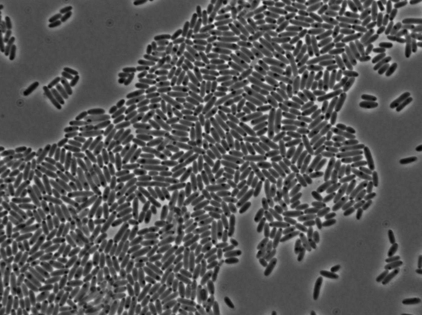
First we launch cells from the overnight culture tube. Cells are here induced with IPGT. Then we wash the cells and relaunch them with IPTG. This way we are sure that the T7 RNA polymerase gene of BL21 gene will be expressed.
Here we can see that nearly all cells are activated. Their GFP expression is at the maximum the T7 autoloop allows.
Testing the memory of the autoloop
1-First we launch cells from the overnight culture tube without IPGT. Then we wash the cells and relaunch them with IPTG.
Here you can see the same level of fluorescence as the négative control, indicating induction did not had time to occur on the solid medium. After one hour we can see that cells glow at the same level.
2-First we launch cells from the overnight culturetube. Cells are induced with IPGT. Then we wash the cells and relaunch them with glucose to inhibit T7 RNA polymerase expression in BL21.
l Here cells are strongly glowing. That means they show some ability to keep their expression even after repressing the expression of T7 polymerase. Our T7 autoloop can keep a memory of its previous state, at least for a few dozens of minutes (the time we needed to wash and relaunch them with glucose), which is exactly what we need for our diffusion experiments. After one hour we can see that cells glow at the same level. This could mean that the system have a memory that make cells keep their first phenotype even after one hour of inhibition by glucose.
Testing the nanotubes with this design

|
T7 RNA polymerase diffusion In this design, we introduce the use of the T7 polymerase both as the transfer molecule and as the auto-amplification system. We were able to do E.coli to B.subtilis as well as B.subtilis-B.subtilis diffusion through nanotubes experiment with this design. We also tried to experiment with our microfluidic chip with this design. |
 "
"


