Team:Paris Bettencourt/Experiments/T7 diffusion experiments
From 2011.igem.org

Testing nanotubes with T7 RNA polymerase diffusion
Summary
All our experiments followed our microscopy protocol when not specified otherwise.
Results for the YFP concentrator:
- We've done E.coli to B.subtilis (T7 autoloop in a plasmid) diffusion experiments (with negative results)
- We've done B.subtilis to B.subtilis (T7 autoloop in a plasmid and in the genome) diffusion experiments (with negative results)
- We've done B.subtilis to B.subtilis (chromosomal T7 autoloop) diffusion experiments in our microfluidic chip observed indirect evidence of nanotube-assisted diffusion
Design overview

Schematic summary of the T7 diffusion device
All of the parts of the above design have been BioBricked, characterized both in E.coli and B.subtilis, and sent to the registry.
More details on the design are available here.
Emitter construct in E.coli - Receiver construct in B.subtilis (plasmid)
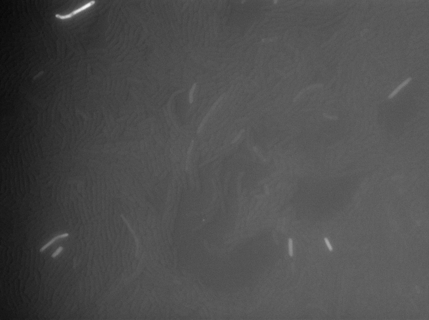
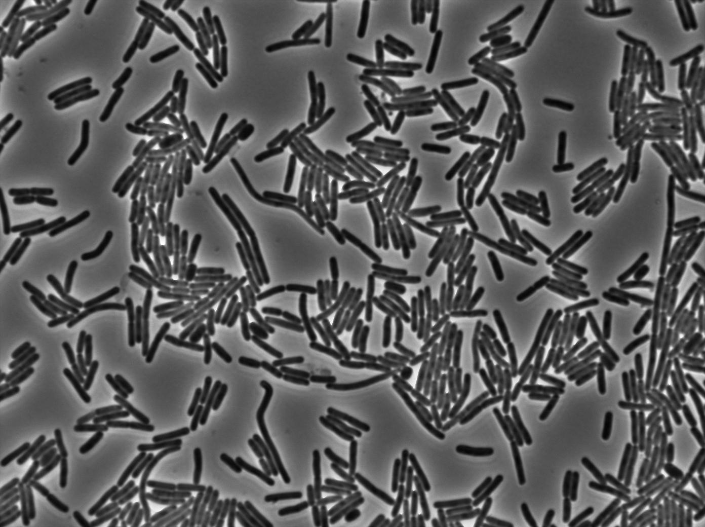
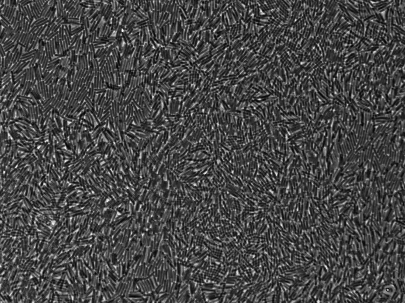
As a control for Coli to Subtillis diffusion we wanted to use E.Coli as an T7 RNA Polymerase emitter and B.Subtillis as theT7 autoloop reciever. Here we can see pictures taken using our classic microscopy protocol.As the pictures show, there is no new highly glowing cell after 125 minutes experimentation.
Emitter & receiver constructs in B.subtilis (receiver in plasmid)
As a first trial we cloned our system into the PHM3 plasmid. This experimentation represents the first Subtillis to Subtillis signal diffusion we clearly designed.
Here also, we can see no obvious increase of fluorescence over time.
Emitter & receiver constructs in B.subtilis (receiver in genome)
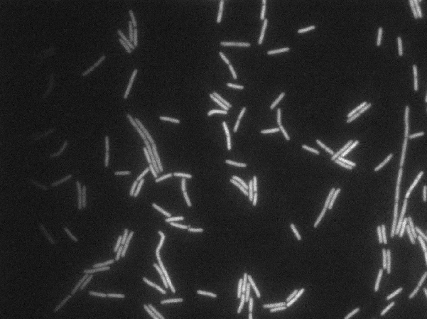
We used our microscopy protocol to do this experiment. The emitter strain is a B.subtilis PY9 strain where our emitter construct is integrated in the genome. The receiver strain is a B.subtilis PY9 strain where our T7 autoloop (receiver) construct is integrated in the genome.
We followed our cultures on three microscopic slides: one for the emitter, one for the receiver and one for the mix.
Again, we can see no increase of fluorescence in our mix over time.
Using the microfluidic chip (B.subtilis/B.subtilis)

|
Our microfluidic experiment gave some indirect evidence of nanotube-assisted diffusion of T7 RNA polymerase. We used for this experiment two B.subtilis strains (one emitter, one receiver, both integrated in the genome). Our chromosomal T7 autoloop was brightly activated during this experiment, but only in densely packed mix of emitter and receiver cells. Since it is a complicated experiment, it deserves its own specific page. Find more about this experiment here. |
Concentrating the cells more for microscopy (B.subtilis/B.subtilis)
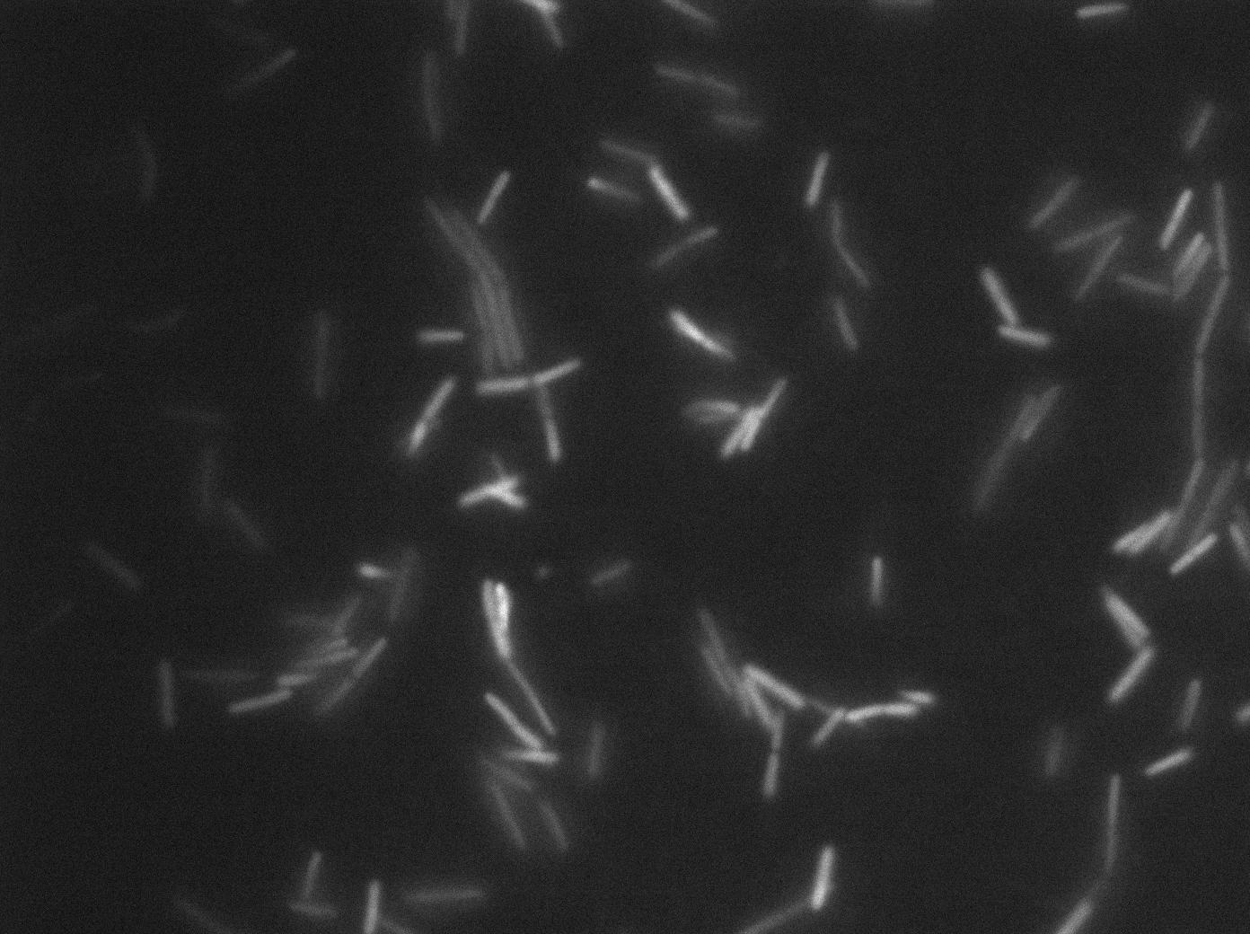
We followed our cultures on three microscopic slides: one for the emitter, one for the receiver and one for the mix. The main difference here is we had the previous results from the microfluidic chip. We know that the chromosomal T7 autoloop can be activated in special conditions. We tried to put the cells in a highly dense pack where such events could happen more often.
Once again, no increase of fluorescence was observed.
FACS experiments
Protocol: Cells in exponential phase are concentrated on a filter to favour nanotubes formation. The filters are incubated on LB plates for different times (here from 0 to 90 min) and then put in MgSO4 10-2M H20 to solubilize cells. Cells are subsequently diluted in PBS for the FACS.
 |
 |
 |
 |
 |
| Receiver cells after 0 min incubation | Emitter cells after 0 min incubation | Emitter-Receiver (1:1 ratio) mix cells after 0 min incubation | Emitter-Receiver (1:5 ratio) mix cells after 0 min incubation | Emitter-Receiver (5:1 ratio) mix cells after 0 min incubation |

|

|

|

|

|
| Receiver cells after 40 min incubation | Emitter cells after 0 min incubation | Emitter-Receiver (1:1 ratio) mix cells after 40 min incubation | Emitter-Receiver (1:5 ratio) mix cells after 40 min incubation | Emitter-Receiver (5:1 ratio) mix cells after 40 min incubation | 
|

|

|

|

|
| Receiver cells after 40 min incubation | Emitter cells after 40 min incubation | Emitter-Receiver (1:1 ratio) mix cells after 90 min incubation | Emitter-Receiver (1:5 ratio) mix cells after 90 min incubation | Emitter-Receiver (5:1 ratio) mix cells after 90 min incubation |
Conclusions
During all of our experiments with the T7 polymerase diffusion we did not see any fluorescence increase (in the case of the plasmidic autoloop) nor fluorescence appearance (in the case of the chromosomal autoloop). We put our cells in the same conditions that we used in the successful GFP diffusion experiments as well as some new ones. All these repeated testing with T7 RNA polymerase diffusion design shows no evidence of nanotube existence so far. We are currently continuing our experiments to further explore the system.
Limits
Our plasmidic autoloop is very leaky and it is quite hard to see obvious increase in fluorescence. With even finer tuning of our experimental conditions, we might be able to see better a possible hint of nanotube presence.
Our chromosomal autoloop has not been fully tested yet. We are currently trying to put it in the same cell that the T7 RNA polymerase gene to activate it all the time. The total absence of leakage under the microscope seemed quite suspect at first but we saw that it could be activated in the microfluidic experiment. Further investigation on this matter is under way. We are very excited about this construct because it might allow us to have a high signal-to-noise ratio.
We also need to properly test the T7 RNA polymerase we put in B.subtilis, for instance by putting a plasmidic pT7-GFP construct. However, since it is the same gene as in our pHM3 T7 autoloop, we already have indirect proof of its functionality.
 "
"


