Team:ETH Zurich/Process/Microfluidics
From 2011.igem.org
(→Microfluidic channel with flow and recycling of the medium) |
(→Further improvements: Microfluidic Channels with epoxy, molten parafilm or silicon) |
||
| (57 intermediate revisions not shown) | |||
| Line 2: | Line 2: | ||
{{:Team:ETH Zurich/Templates/SectionStart}} | {{:Team:ETH Zurich/Templates/SectionStart}} | ||
= Microfluidic Channel Design = | = Microfluidic Channel Design = | ||
| - | ''' | + | '''For implementation of the SmoColi system, a channel is needed to establish a small molecule gradient (see [[Team:ETH_Zurich/Overview/Informationprocessing|Information processing]]). However, there were several different possible channel designs, and the final design evolved through an iterative series of design steps and design validations. The first designs were validated based on vast simulations, the final design furthermore by biological experiments in the lab (see [[Team:ETH_Zurich/Process/Validation|Systems Validation]]).''' |
{{:Team:ETH Zurich/Templates/SectionEnd}} | {{:Team:ETH Zurich/Templates/SectionEnd}} | ||
{{:Team:ETH Zurich/Templates/SectionStart}} | {{:Team:ETH Zurich/Templates/SectionStart}} | ||
== Microfluidic channel with flow and recycling of the medium == | == Microfluidic channel with flow and recycling of the medium == | ||
| - | We came up with two different possible microfluidic channel designs, both involving immobilized cells and | + | We came up with two different possible '''microfluidic channel designs''', both involving immobilized cells and a flow of medium containing inducer molecules through the channel. By having a flow and degradation, we could obtain a '''gradient of the inducer molecule'''. Because of the flow, our cells would also be constantly supplied with nutrients from the medium. |
| + | |||
* '''Variant 1: Microfluidic channel with agarose-immobilized cells in cubic pockets''' | * '''Variant 1: Microfluidic channel with agarose-immobilized cells in cubic pockets''' | ||
| - | |||
| - | The cell-agarose | + | This channel design consists of two layers: The bottom one is a polydimethylsiloxane (PDMS) plate with regular cubic pockets. These pockets are filled with agarose-immobilized cells by letting the cell-agarose suspension flow over the pockets from the top by gravity. After washing the channel, cells would only be retained in the pockets. <br> <br> |
| + | |||
| + | The top layer is the actual PDMS channel, which is several pixels wide and several pixels high. Although this setup is rather complex, it has the advantage of having immobilized cells and thus being more robust, i.e. we could vary flow speeds or even put aerosol in the channel without the cells being washed out. Additionally, cell density can be varied very easily in this design as the cells can be diluted before being immobilized in agarose. | ||
| + | |||
| - | |||
{|style="border: none;" align="center" | {|style="border: none;" align="center" | ||
| - | |valign="top"|[[File:flowchannel_pixel.png|500px|center|thumb|'''Figure 1: Experimental setup for SmoColi, Variant 1. ''' ]] | + | |valign="top"|[[File:flowchannel_pixel.png|500px|center|thumb|'''Figure 1: Experimental setup for SmoColi channel, Variant 1. ''' ]] |
|valign="top"|<html> | |valign="top"|<html> | ||
<div class="thumb tright"><div class="thumbinner" style="width:402px;"> | <div class="thumb tright"><div class="thumbinner" style="width:402px;"> | ||
| Line 24: | Line 26: | ||
|} | |} | ||
| - | |||
| - | + | * '''Variant 2: Microfluidic channel with cells sitting in pockets inside the channel''' | |
| - | + | ||
| - | |||
| - | + | This channel design only consists of one part: A PDMS channel that is fixed onto a glass carrier. The PDMS channel contains pockets which "trap" the cells given a constant flow from the direction of the "open end" of the pockets. This channel design does not have the advantages of the above one, i.e. it is not as robust and cell density cannot be reliably varied. However, manufacturing it is a standard process and thus it is easier. | |
| - | + | ||
| - | + | ||
| - | |||
| - | |||
| - | |||
| - | + | [[File:flowchannel_pockets.png|400px|center|thumb|'''Figure 2: Experimental setup for SmoColi channel, Variant 2. The flow is supplied from the right side of the illustration.''' ]]<br clear="all" /> | |
| - | |||
| - | + | '''Problems with these design variants:''' <br> <br> | |
| - | + | A problem with both of these designs is that for the AHL-based RFP alarm to work, recycling of the flow back into the channel would be required. AHL-producing cells are only those "after" the GFP band, i.e. those at lower acetaldehyde concentration than the band concentration range. As long as the GFP band has not arrived to the end of the channel, we should make sure that there is AHL everywhere in the channel, so that it inhibits RFP production in every cell. Modeling showed that AHL can not simply diffuse "backwards" against the flow, but by having a recycling all the cells would be supplied with AHL and thus the alarm won't be activated before time. | |
| - | + | ||
| - | + | ||
| - | + | However, since the tubing and pumps would have very high volumes compared to the channel's volume, the AHL signal would be diluted to the point where no detection is possible anymore. Also, several pumps would be required to accomplish this, further complicating the process design and making it more error-prone. <br><br> | |
| - | + | {{:Team:ETH Zurich/Templates/SectionEnd}} | |
| + | {{:Team:ETH Zurich/Templates/SectionStart}} | ||
| - | + | == Improved microfluidic channel without flow == | |
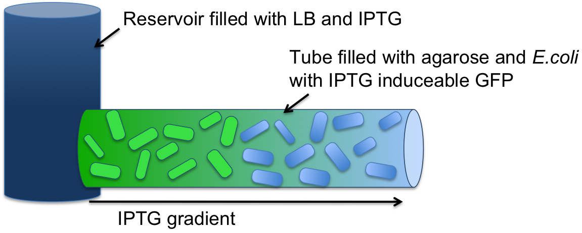
| + | [[File:Setup_test.png|500px|right|thumb|'''Figure 3: Experimental setup for SmoColi, a tube with no flow, diffusion only''' ]] | ||
| + | Modeling showed that '''diffusion and degradation of the inducer is enough''' to create a concentration gradient in the channel. For proof of concept, we engineered E. coli strain JM101 to express GFP upon IPTG induction. The cells were immobilized in agarose and the suspension was added to the tube. One end of the tube was connected to a resevoir containing a IPTG solution. After incubation overnight, an IPTG-inducible GFP gradient could be observed. The experiment confirmed the modeling results. ''E. coli'' remained viable and we concluded that no flow was needed in our system setup. For more information about this [[Team:ETH Zurich/Process/Microfluidics/Proof|experimental setup and quantification of the results click here.]]<br><br> | ||
| - | + | '''Problem with this design variant''': <br><br>No live imaging is possible, but only end point measurements, since the agarose with cells first has to be taken out of the tube and then analyzed under microscope. | |
| - | + | ||
| - | + | ||
| - | + | ||
| - | + | ||
| - | '''Problem with this design variant''': No live imaging is possible, but only end point measurements, since the agarose with cells first has to be taken out of the tube and then analyzed under microscope. | + | |
{{:Team:ETH Zurich/Templates/SectionEnd}} | {{:Team:ETH Zurich/Templates/SectionEnd}} | ||
{{:Team:ETH Zurich/Templates/SectionStart}} | {{:Team:ETH Zurich/Templates/SectionStart}} | ||
| - | == Further improvements: Microfluidic Channels with | + | |
| - | + | == Further improvements: Microfluidic Channels with epoxy, molten parafilm or silicon == | |
| + | Since live imaging in the tube was not possible, we tried to further improve our design to meet our experimental requirements. Thus we tried to pour our own channel with a reservoir included. Different substances as epoxy, molten parafilm or silicon were tested. As a mask we used plastic which we cut by hand. | ||
| + | The channel was put on a object slide after solidification. Then the agarose-''E. coli'' suspension could be poured inside the channel. | ||
| + | |||
{|style="border: none;" align="center" | {|style="border: none;" align="center" | ||
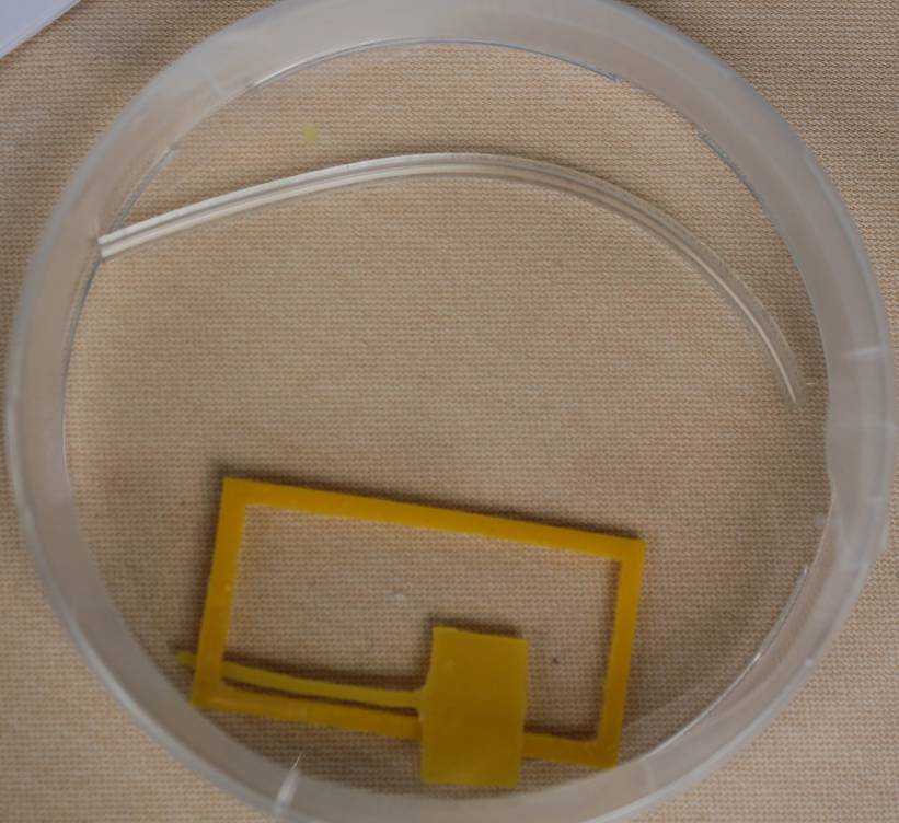
| - | |valign="top"|[[File:ETHZ_channel1.jpg|350px|center|thumb|'''Figure | + | |valign="top"|[[File:ETHZ_channel1.jpg|350px|center|thumb|'''Figure 4''': Tube (up) and plastic mask for channel construction (bottom) ]] |
| - | |valign="top"|[[File:ETHZ_channel2.jpg|410px|center|thumb|'''Figure | + | |valign="top"|[[File:ETHZ_channel2.jpg|410px|center|thumb|'''Figure 5''': Construction of microfluidic channels with silicon glue (left) and epoxy (right)]] |
|} | |} | ||
| - | |||
| - | + | '''Problems with this design:'''<br><br> | |
| + | The glue turned out to be toxic for our cells.<br> | ||
| + | We could also not use molten parafilm, since after putting it on the mask, the parafilm stuck to it and we could not remove the mask any more without destroying the channel (for molten parafilm a plastic mask is needed). <br> | ||
| + | For silicon, we could get rid of this problem by covering the mask with oil. However, we had a problem with closing the channel tightly to prevent evaporation. Since this problem would occur with all of our designs, we decided to change it again. | ||
| + | |||
{{:Team:ETH Zurich/Templates/SectionEnd}} | {{:Team:ETH Zurich/Templates/SectionEnd}} | ||
{{:Team:ETH Zurich/Templates/SectionStart}} | {{:Team:ETH Zurich/Templates/SectionStart}} | ||
| Line 77: | Line 72: | ||
== Final Design: Microfluidics channel with PDMS == | == Final Design: Microfluidics channel with PDMS == | ||
| - | Finally, we decided to construct our channels out of PDMS ( | + | Finally, we decided to construct our channels out of something more frequently used: '''PDMS (polydimethylsiloxane)'''. To construct the channel, a technique called '''photolithography''' was used. Advantages of PDMS are that it is cheap, optically clear and permeable to several substances, including gases (air can quickly diffuse through) [[#Ref1|[1]]]. For the PDMS as well, as for the silicon channel we had problems with water evaporation. In order to solve this issue, in our final experimental setup we incubated the chips chontaining the channels in a petri dish full of water.<br> |
| - | + | We constructed the PDMS channels ourselves, which was a very fun and interesting process. Our final design and the channel construction is explained in details [[Team:ETH_Zurich/Process/Validation|here]]. | |
| - | We constructed the channels ourselves, which was very fun and interesting process. Our final design and the | + | |
{{:Team:ETH Zurich/Templates/SectionEnd}} | {{:Team:ETH Zurich/Templates/SectionEnd}} | ||
{{:Team:ETH Zurich/Templates/SectionStart}} | {{:Team:ETH Zurich/Templates/SectionStart}} | ||
Latest revision as of 00:42, 29 October 2011
Microfluidic Channel Design
For implementation of the SmoColi system, a channel is needed to establish a small molecule gradient (see Information processing). However, there were several different possible channel designs, and the final design evolved through an iterative series of design steps and design validations. The first designs were validated based on vast simulations, the final design furthermore by biological experiments in the lab (see Systems Validation).
Microfluidic channel with flow and recycling of the medium
We came up with two different possible microfluidic channel designs, both involving immobilized cells and a flow of medium containing inducer molecules through the channel. By having a flow and degradation, we could obtain a gradient of the inducer molecule. Because of the flow, our cells would also be constantly supplied with nutrients from the medium.
- Variant 1: Microfluidic channel with agarose-immobilized cells in cubic pockets
This channel design consists of two layers: The bottom one is a polydimethylsiloxane (PDMS) plate with regular cubic pockets. These pockets are filled with agarose-immobilized cells by letting the cell-agarose suspension flow over the pockets from the top by gravity. After washing the channel, cells would only be retained in the pockets.
The top layer is the actual PDMS channel, which is several pixels wide and several pixels high. Although this setup is rather complex, it has the advantage of having immobilized cells and thus being more robust, i.e. we could vary flow speeds or even put aerosol in the channel without the cells being washed out. Additionally, cell density can be varied very easily in this design as the cells can be diluted before being immobilized in agarose.
- Variant 2: Microfluidic channel with cells sitting in pockets inside the channel
This channel design only consists of one part: A PDMS channel that is fixed onto a glass carrier. The PDMS channel contains pockets which "trap" the cells given a constant flow from the direction of the "open end" of the pockets. This channel design does not have the advantages of the above one, i.e. it is not as robust and cell density cannot be reliably varied. However, manufacturing it is a standard process and thus it is easier.
Problems with these design variants:
A problem with both of these designs is that for the AHL-based RFP alarm to work, recycling of the flow back into the channel would be required. AHL-producing cells are only those "after" the GFP band, i.e. those at lower acetaldehyde concentration than the band concentration range. As long as the GFP band has not arrived to the end of the channel, we should make sure that there is AHL everywhere in the channel, so that it inhibits RFP production in every cell. Modeling showed that AHL can not simply diffuse "backwards" against the flow, but by having a recycling all the cells would be supplied with AHL and thus the alarm won't be activated before time.
However, since the tubing and pumps would have very high volumes compared to the channel's volume, the AHL signal would be diluted to the point where no detection is possible anymore. Also, several pumps would be required to accomplish this, further complicating the process design and making it more error-prone.
Improved microfluidic channel without flow
Modeling showed that diffusion and degradation of the inducer is enough to create a concentration gradient in the channel. For proof of concept, we engineered E. coli strain JM101 to express GFP upon IPTG induction. The cells were immobilized in agarose and the suspension was added to the tube. One end of the tube was connected to a resevoir containing a IPTG solution. After incubation overnight, an IPTG-inducible GFP gradient could be observed. The experiment confirmed the modeling results. E. coli remained viable and we concluded that no flow was needed in our system setup. For more information about this experimental setup and quantification of the results click here.
Problem with this design variant:
No live imaging is possible, but only end point measurements, since the agarose with cells first has to be taken out of the tube and then analyzed under microscope.
Further improvements: Microfluidic Channels with epoxy, molten parafilm or silicon
Since live imaging in the tube was not possible, we tried to further improve our design to meet our experimental requirements. Thus we tried to pour our own channel with a reservoir included. Different substances as epoxy, molten parafilm or silicon were tested. As a mask we used plastic which we cut by hand. The channel was put on a object slide after solidification. Then the agarose-E. coli suspension could be poured inside the channel.
Problems with this design:
The glue turned out to be toxic for our cells.
We could also not use molten parafilm, since after putting it on the mask, the parafilm stuck to it and we could not remove the mask any more without destroying the channel (for molten parafilm a plastic mask is needed).
For silicon, we could get rid of this problem by covering the mask with oil. However, we had a problem with closing the channel tightly to prevent evaporation. Since this problem would occur with all of our designs, we decided to change it again.
Final Design: Microfluidics channel with PDMS
Finally, we decided to construct our channels out of something more frequently used: PDMS (polydimethylsiloxane). To construct the channel, a technique called photolithography was used. Advantages of PDMS are that it is cheap, optically clear and permeable to several substances, including gases (air can quickly diffuse through) [1]. For the PDMS as well, as for the silicon channel we had problems with water evaporation. In order to solve this issue, in our final experimental setup we incubated the chips chontaining the channels in a petri dish full of water.
We constructed the PDMS channels ourselves, which was a very fun and interesting process. Our final design and the channel construction is explained in details here.
References
[1] [http://www.elveflow.com/microfluidic/16-start-with-microfluidic http://www.elveflow.com/microfluidic/16-start-with-microfluidic]
 "
"

