Team:Bielefeld-Germany/Black-box
From 2011.igem.org
(→Beacon Box) |
|||
| (One intermediate revision not shown) | |||
| Line 3: | Line 3: | ||
==Beacon Box== | ==Beacon Box== | ||
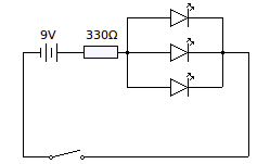
| - | [[File:Bielefeld-Germany2011-circuit.png|250px|thumb|right|Figure 1: Circuit diagram for the Beacon Box circuit board]] | + | [[File:Bielefeld-Germany2011-circuit.png|250px|thumb|right|Figure 1: Circuit diagram for the Beacon Box circuit board.]] |
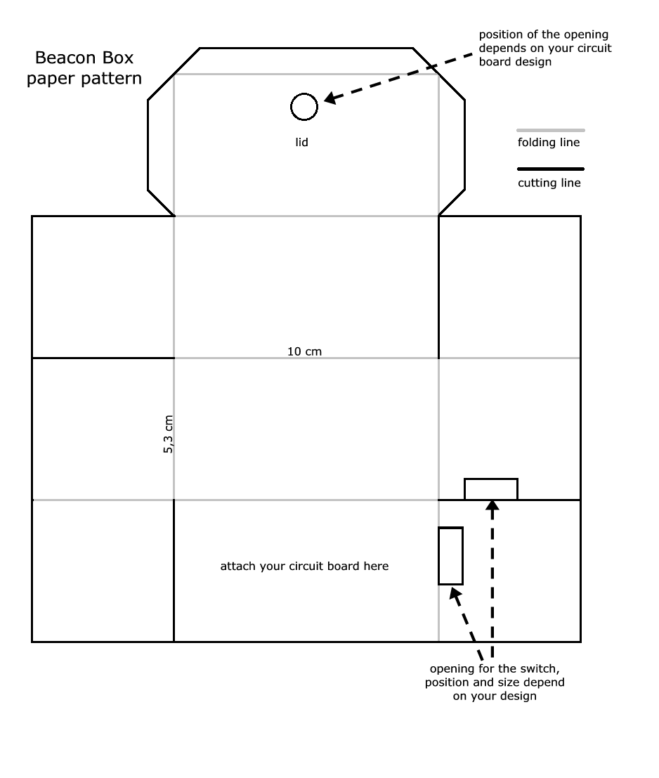
| - | [[File:Bielefeld-Germany-2011-Paper_Pattern.png|250px|thumb|rigth|Figure 2: Beacon Box paper pattern]] | + | [[File:Bielefeld-Germany-2011-Paper_Pattern.png|250px|thumb|rigth|Figure 2: Beacon Box paper pattern.]] |
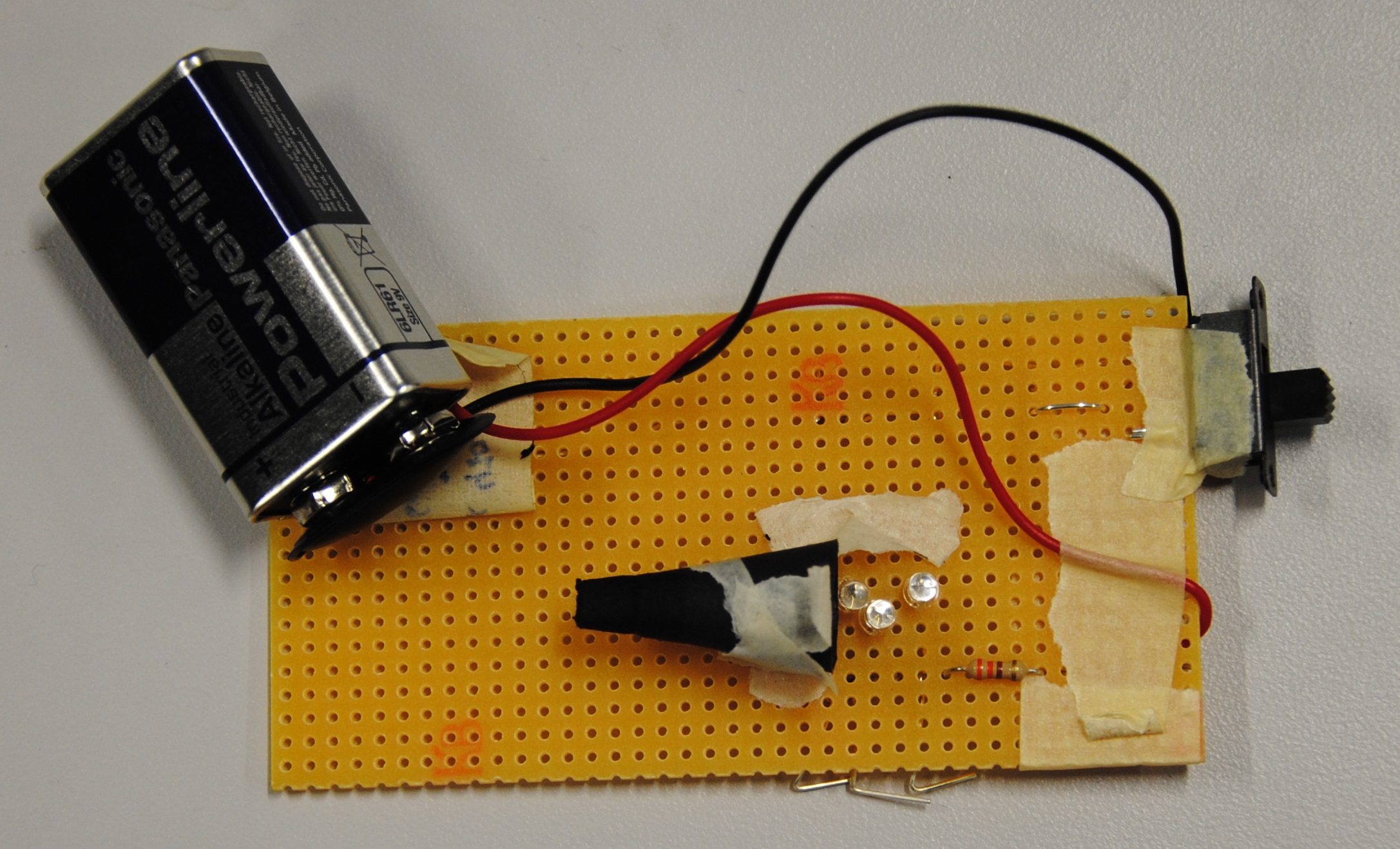
| - | [[File:Bielefeld-Germany2011-circuitboard.png|250px|thumb|right|Figure 3: Circuit board]] | + | [[File:Bielefeld-Germany2011-circuitboard.png|250px|thumb|right|Figure 3: Circuit board.]] |
[[File:Bielefeld-Germany-2011-Beacon-Box-Closed.JPG|250px|thumb|right|Figure 4: The outer appearance of the Beacon Box with closed front.]] | [[File:Bielefeld-Germany-2011-Beacon-Box-Closed.JPG|250px|thumb|right|Figure 4: The outer appearance of the Beacon Box with closed front.]] | ||
| Line 17: | Line 17: | ||
*power source (9 V) and switch | *power source (9 V) and switch | ||
*electrical resistance: 330 Ω | *electrical resistance: 330 Ω | ||
| - | *three blue <html><span id="igem-tooltip" style="font-size:12px;"><a href="http://www.led1.de/shop/lng/en/standard-leds/led-3mm-ultra-bright/led-3mm-blue-6000mcd-webbl06-cs.html?type=N&language=en" title="We used this LED:<br/> WEBBL06-CS by Winger Electronics GmbH & Co. KG:<br/> Voltage 3.2 mV,<br/> 20 mA,<br/> 0.1 W,<br/>Brightness 6000 mcd,<br/>Wavelengh 470 nm,<br/> 96% color purity">LEDs</a></span></html> | + | *three blue <html><span id="igem-tooltip" style="font-size:12px;"><a href="http://www.led1.de/shop/lng/en/standard-leds/led-3mm-ultra-bright/led-3mm-blue-6000mcd-webbl06-cs.html?type=N&language=en" title="We used this LED:<br/> WEBBL06-CS by Winger Electronics GmbH & Co. KG:<br/> Voltage 3.2 mV,<br/> 20 mA,<br/> 0.1 W,<br/>Brightness 6000 mcd,<br/>Wavelengh 470 nm,<br/> 96 % color purity">LEDs</a></span></html> |
| - | Now you can solder the parts to the board according to the circuit diagram (figure 1). You need to attach the three LEDs in close proximity to reduce scattering. | + | Now you can solder the parts to the board according to the circuit diagram (figure 1). You need to attach the three LEDs in close proximity to reduce scattering. |
| - | The next task is to build the box itself. Cut out the box from solid paper according to the paper pattern (figure 2). The position for the opening in the lid and the opening for the switch depend on your circuit board design (figure 3). Fold the Beacon Box at the grey lines of the paper pattern and crease the folds firmly. Now you need to fold up the side parts of the box and glue the overlapping ends to the inner side of the adjacent side part. | + | The next task is to build the box itself. Cut out the box from solid paper according to the paper pattern (figure 2). The position for the opening in the lid and the opening for the switch depend on your circuit board design (figure 3). Fold the Beacon Box at the grey lines of the paper pattern and crease the folds firmly. Now you need to fold up the side parts of the box and glue the overlapping ends to the inner side of the adjacent side part. |
The following part is the construction of the cone that you put over the LEDs on your board. Cut out a quarter circle. You might use leftover paper from your box. Now roll up the paper to a cone (smooth the paper on an edge of your desk beforehand) and cut off the top. The cone is supposed to be put over the LEDs, so the diameter of the base needs to be large enough, but to reduce the scattering the diameter also needs to be as small as possible. Later on, a PCR tube is plugged on the top of the cone, so firstly the cone must not be too high (it still needs to have enough space for attaching and removing the tube). Secondly the cone has to possess the right diameter at the cut-off side so that a PCR tube stays attached to the cone while the cone is upside down. | The following part is the construction of the cone that you put over the LEDs on your board. Cut out a quarter circle. You might use leftover paper from your box. Now roll up the paper to a cone (smooth the paper on an edge of your desk beforehand) and cut off the top. The cone is supposed to be put over the LEDs, so the diameter of the base needs to be large enough, but to reduce the scattering the diameter also needs to be as small as possible. Later on, a PCR tube is plugged on the top of the cone, so firstly the cone must not be too high (it still needs to have enough space for attaching and removing the tube). Secondly the cone has to possess the right diameter at the cut-off side so that a PCR tube stays attached to the cone while the cone is upside down. | ||
| - | Next you attach the circuit board to your box, add molecular beacons and complementary target to a PCR tube and attach it to the cone. Close the lid of the box, switch on the LEDs and look through the opening in the lid. The green shimmering in the tube is what you want to see - fluorescent molecular beacons in their open state (figure 5). | + | Next you attach the circuit board to your box, add molecular beacons and complementary target to a PCR tube and attach it to the cone. Close the lid of the box, switch on the LEDs and look through the opening in the lid. The green shimmering in the tube is what you want to see - fluorescent molecular beacons in their open state (figure 5). |
| - | [[File:Bielefeld-Germany2011-beaconbox.png|550px|none|thumb|Figure 5: Visualization of the molecular beacons fluorescence upon hybridization to a complementary target. The Beacon Box is shown with opened lid. Left: PCR tube filled with 500 nM molecular beacon and 600 nM complementary target. Right: PCR tube filled with molecular beacon alone]] | + | [[File:Bielefeld-Germany2011-beaconbox.png|550px|none|thumb|Figure 5: Visualization of the molecular beacons fluorescence upon hybridization to a complementary target. The Beacon Box is shown with opened lid. Left: PCR tube filled with 500 nM molecular beacon and 600 nM complementary target. Right: PCR tube filled with molecular beacon alone.]] |
Latest revision as of 00:12, 22 September 2011

Beacon Box
To give the audience of our Science Cafe-talk an impression of the molecular beacon reaction we constructed a "Beacon Box". The box has an easy design and can be rebuilt at home, just some basic skills in handicraft and electrical engineering are necessary.
First of all you need to obtain the electronic equipment:
- circuit board and some wires
- soldering iron and soldering wire
- power source (9 V) and switch
- electrical resistance: 330 Ω
- three blue LEDs
Now you can solder the parts to the board according to the circuit diagram (figure 1). You need to attach the three LEDs in close proximity to reduce scattering.
The next task is to build the box itself. Cut out the box from solid paper according to the paper pattern (figure 2). The position for the opening in the lid and the opening for the switch depend on your circuit board design (figure 3). Fold the Beacon Box at the grey lines of the paper pattern and crease the folds firmly. Now you need to fold up the side parts of the box and glue the overlapping ends to the inner side of the adjacent side part.
The following part is the construction of the cone that you put over the LEDs on your board. Cut out a quarter circle. You might use leftover paper from your box. Now roll up the paper to a cone (smooth the paper on an edge of your desk beforehand) and cut off the top. The cone is supposed to be put over the LEDs, so the diameter of the base needs to be large enough, but to reduce the scattering the diameter also needs to be as small as possible. Later on, a PCR tube is plugged on the top of the cone, so firstly the cone must not be too high (it still needs to have enough space for attaching and removing the tube). Secondly the cone has to possess the right diameter at the cut-off side so that a PCR tube stays attached to the cone while the cone is upside down.
Next you attach the circuit board to your box, add molecular beacons and complementary target to a PCR tube and attach it to the cone. Close the lid of the box, switch on the LEDs and look through the opening in the lid. The green shimmering in the tube is what you want to see - fluorescent molecular beacons in their open state (figure 5).
 "
"


