 "
"
Team:ENSPS-Strasbourg/Project
From 2011.igem.org
Choice of the tools
The first step was to choose a programming language suitable for making our implementation. Ideally, we wanted to use the same language to program both GUI and file generation. In a previous project, we have already programed a GUI, in C++ language, with the framework QT creator. Moreover, the C++ is a powerful multi-purpose language which could be suitable for making our file generation. Another advantage of C++ is that we have a C/C++ programming module in our course, and we thought that it was probably better to implement this program with a language we already knew. We have so decided to use C++, for its versatility, and because we are quite used to it.
Qt creator – presentation
Then, we need to find an electronic circuit simulator which enables us to simulate the systems as electronic systems. For that, we choose SMASH (Dolphin), because this software is one of the most accomplished simulation software, so as to simulate both digital and analog electronics. SMASH - presentation
Version 1 - « Behavioral Code Generator »
Introduction
The first step of the project was to validate the concept of the program. We have so decided to build a first version of the software, with simple digital models. This version, entitled “Behavioral Code Generator”, enables the user to simulate a logic version of the mechanisms and reactions.
Approach
The aim of this first implementation is to validate the idea of building a software which generates automatically models for each reaction of a system. Those models are electrical models of two basic biological mechanisms, written in VHDL for the first time, as seen in the[Models LIEN VERS MODELES VHDL] section. After that, this generation can be simulated directly with an electronic circuit simulator, as a digital electronic circuit.
File generation
The goal is to generate automatically VHDL files which are representative of the different reactions of the system. For that, our approach is to use pattern files, and to fill up those files with the right variables (species, names…), depending on the reactions implemented by the user.
To simulate a system, the electric simulator needs several files:
• One VHDL description per entity
• A test-bench file
"Principle:"
At each entity (or each reaction) corresponds a VHDL file. An example of VHDL pattern file is available below:
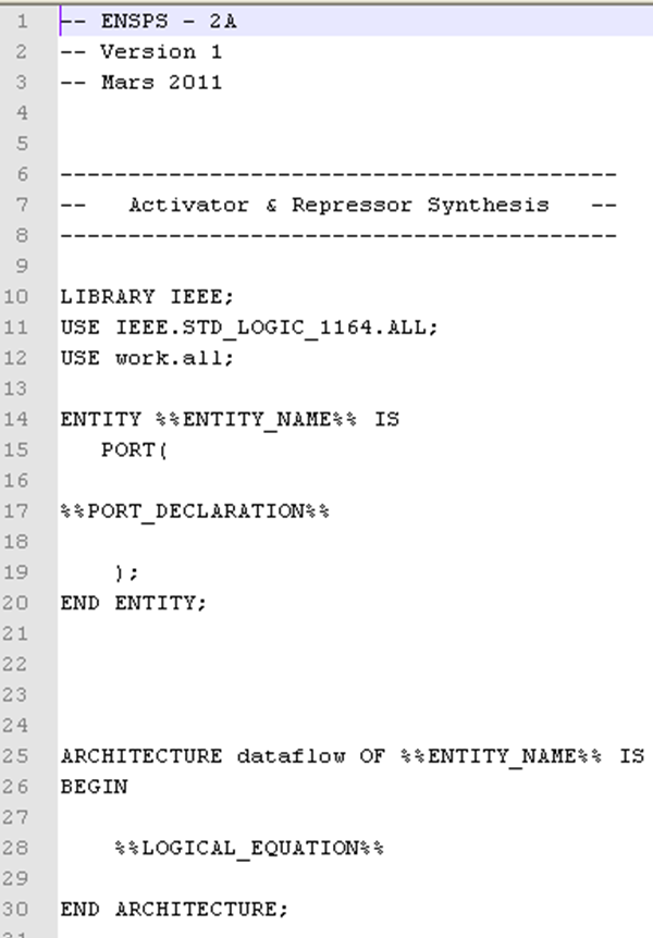
This file defines the structure of all the VHDL files which will contain a synthesis reaction. It is the same file for every synthesis reaction the user will create. Then, several parameters have to be changed. All the expressions between the symbols “%%” are attributes of the reaction:
• ENTITY_NAME: Name of the reaction (given by the user)
• PORT_DECLARATION: This section will contain the different variables (species) of the reaction, and if those species are inputs or outputs
• LOGICAL_EQUATION: In this section, the model of the reaction, described by a logical equation, is inserted so as to have the right behavior between inputs and outputs
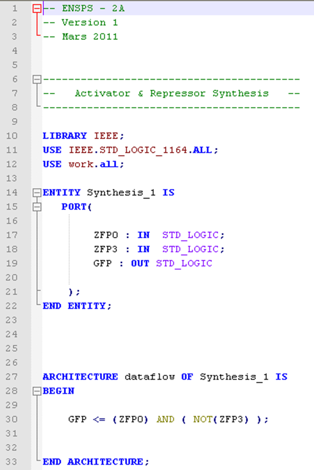
In the image below, you can see a correctly filled pattern file. Indeed, the entity name has been replaced by the name of the reaction given by the user, the different species involved into the reaction ( ZFP0 and ZFP3 in input, GFP in output), are correctly mapped, and the logical equation is automatically established (in this case GFP is synthetized only if there is ZFP0 (the activator) and not ZFP3 (the repressor) ).
How it works?
The C++ code, linked with the GUI, stock the different species and reactions involved in the system. A special Class architecture of the code, based on heritage, enables the program to know exactly which species are involved in which reaction. Some tables list the species, their type, and their initial values. Then, for each reaction created, the program replaces the different variables as follows: