 "
"
Team:ENSPS-Strasbourg/Project
From 2011.igem.org
Introduction
Choice of the tools
The first step was to choose a programming language suitable for making our implementation. Ideally, we wanted to use the same language to program both GUI and file generation. In a previous project, we have already programed a GUI, in C++ language, with the framework QT creator. Moreover, the C++ is a powerful multi-purpose language which could be suitable for making our file generation. Another advantage of C++ is that we have a C/C++ programming module in our course, and we thought that it was probably better to implement this program with a language we already knew. We have so decided to use C++, for its versatility, and because we are quite used to it.
"Qt creator – presentation:"
Qt Creator is an integrated development environment (IDE) that provides tools to design and develop applications with the Qt application framework. Qt is designed for developing applications and user interfaces once and deploying them across several desktop and mobile operating systems.
Then, we need to find an electronic circuit simulator which enables us to simulate the systems as electronic systems. For that, we choose SMASH (Dolphin), because this software is one of the most accomplished simulation software, so as to simulate both digital and analog electronics.
Version 1 - « Behavioral Code Generator »
Introduction
The first step of the project was to validate the concept of the program. We have so decided to build a first version of the software, with digital models. This version, entitled “Behavioral Code Generator”, permits the user to simulate a logic (or behavioral) version of the reactions of his system. This version enables the biologist to have a quick overview on the system, and could be useful for him before going further into the biobrick's conception
Approach
The aim of this first implementation is to validate the idea of building a software which generates automatically models for each reaction of a system. Those models are electrical models of three basic biological mechanisms (inhibition, complexation and synthesis), written in VHDL, as seen in the Models section. After that, this generation can be simulated directly with an electronic circuit simulator, as a digital electronic circuit.
File generation
The goal is to generate automatically VHDL files which are representative of the different reactions of the system. For that, our approach is to use pattern files, and to fill up those files with the right variables (species, names…), depending on the reactions implemented by the user.
To simulate a system, the electric simulator needs several files:
• One VHDL description per entity
• A test-bench file
Entity files
Principle:
At each entity (or each reaction) corresponds a VHDL file. An example of VHDL pattern file is available below:
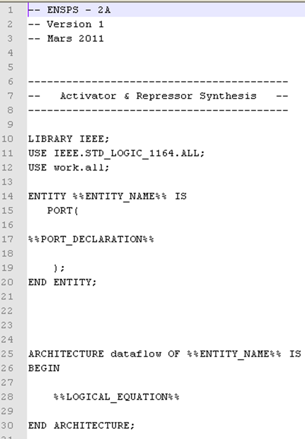
This file defines the structure of all the VHDL files which will contain a synthesis reaction. It is the same file for every synthesis reaction the user will create. Then, several parameters have to be changed. All the expressions between the symbols “%%” are attributes of the reaction:
• ENTITY_NAME: Name of the reaction (given by the user)
• PORT_DECLARATION: This section will contain the different variables (species) of the reaction, and if those species are inputs or outputs
• LOGICAL_EQUATION: In this section, the model of the reaction, described by a logical equation, is inserted so as to have the right behavior between inputs and outputs
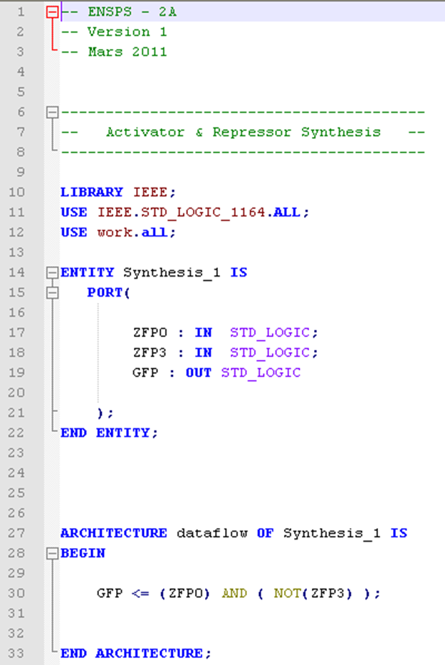
In the image below, you can see a correctly filled pattern file. Indeed, the entity name has been replaced by the name of the reaction given by the user, the different species involved into the reaction ( ZFP0 and ZFP3 in input, GFP in output), are correctly mapped, and the logical equation is automatically established (in this case GFP is synthetized only if there is ZFP0 (the activator) and not ZFP3 (the repressor) ).
How does it work?
The C++ code, linked with the GUI, stock the different species and reactions involved in the system. A special Class architecture of the code, based on heritage, enables the program to know exactly which species are involved in which reaction. This heritage structure is explained in the following scheme:

Basically, each part of this scheme is a class of our implementation. Each of this class has attributes. The question is: What do I need to know to describe each part?
- The system needs to know 1)how the user wants to call it 2)which are the different reactions involved into it
- Each reaction needs to know 1)its name (given by the user), 2)its type (inhibition, complexation or synthesis) and 3) which are the inputs and output species
- Each species of the system needs to know 1)its name, and 2) its initial value
Then, we have all the information we need to start building our system. We have so implented several functions and methods so as to extract, list, classify this information, all this amount of data, and process it to build a system.
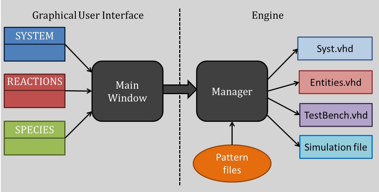
The software architecture is based on two QT main functionalities, the Main Window and the Manager. The Main window is the interface between the software and the user. From this window, the user can talk with the software, enter the species, parameters, reaction, etc… The user builds all the reaction blocks with this interface. Then, to generate automatically the VHDL files associated with the system, the Manager analyses the different reactions, makes links between those blocks and generate the simulation files. This Manager is the crucial part of the architecture, and a lot of work has also been done to make the generation as automatic and reliable as possible. This is the invisible part of the work, the immerged part of the Iceberg. When the user press “generate the system”, this manager is activated and realizes the file generation.
Test Bench Generation
The Test-bench is necessary to perform a good simulation. This file gathers all the reactions of the system, and builds the links between the different reactions. The test-bench generation is the crucial part of the system generation. An example of a test-bench is available below.
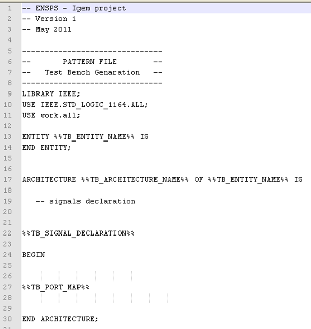
Once again, the principle is the same as entity files. Some parameters have to be added to completely fill the file. The principle of the test bench is so to gather the device's entities (or the system's reactions), and interconnect them together.
- TB_ENTITY_NAME: name of the system (given by the user)
- TB_ARCHITECTURE_NAME: this name is useful for the simulation, and is automatically generated by the program. It is a VHDL specificity, so we are not going into detail here.
- TB_SIGNAL_DECLARATION: the simulator needs to know how many different variables (species) there are into the system. THose variables as represented as signals (another VHDL specificity). So, the program has to list all the species involved, and associate to them a signal.
- TB_PORT_MAP: This is the crucial part of our work. To perform a simulation, the simulation needs to know how each entity (reaction) is connected. Until know, we have just implemented several blocks separately. Now, those blocks have to be interconnected together.
Then, thanks to the Manager code architecture, the test bench is filled with the right values. An example can be seen below.

The important part of the test bench is to gather the different components (reactions), and to map them so as to build the system. For gathering the different reactions, there are no specific issues for complexation and synthesis, but the interconnection is getting trickier with the inhibition (this issue is explained in the “Issue Faced” section below. Basically, the program goes into the different reactions, pick up the species, and if those species are the same the program know that they are interconnected. This mechanisms enables the test-bench generation
Simulation File Generation:
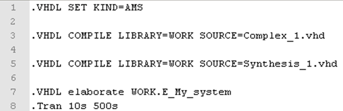
To perform a simulation into SMASH software, we need to create an additional simulation file. This file gathers all the information the simulation software has to know to simulate the system. There are:
• The list of the VHDL entity files (one file per reaction) to know how many components (reactions) are involved
• The name of the test bench (this file will be elaborated to have the whole system)
• The simulation parameters (start and stop simulation times, step of the simulation)
Those parameters are generated automatically, or by the user for the simulation parameters.
Issue Faced
Inhibition
During the implementation of the program, some issues had to be overcome so as to make the file generation properly working.
To gather all the reactions together, the initial approach is to give the same species names, and link those names as illustrated in the figure below.
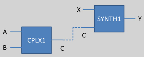
We could imagine than we want to link the output of CPLX1 and one of the input of SYNTH1 (in other words, the protein which is the result of the complexation between A and B is an activator or a repressor for the synthesis of the protein Y). Then, if both has the same name, the link could be done by the implementation.
This principle works for complexation and synthesis, but for inhibition, this association gets trickier. The problem is illustrated below:
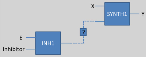
If we want to use a protein (for example E in the above scheme) as an input of another reaction (for example an activator or repressor of SYNTH1), but if this species E can be inhibited by another one, we could not connect directly neither E nor the Inhibitor as an input of the synthesis.
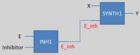
To solve this problem, we have decided to create another species, a fictive species, which is the result of the inhibition (E_inh for example here). Then, we associate this new species as an input for the synthesis reaction. This work has to be done for every species which can be inhibited. This methos is illustrated here:
Version 2 - « Conservative Code Generation »
Introduction
The first version of the program has validated the concept of our program. Then, we could extend this concept to analog models. With a similar approach, we have built an extension of our software which will enable us to simulate conservative models of the bio-system.
Approach
The approach we use is basically the same than the behavioral version. New pattern files have been created to generate VHDL-AMS files. But this new version has several specificities, because of the language used to describe the reactions. Several new files need to be generated in order to build this new system. But, as explained in the Models part, the VHDL-AMS models are totally different from the VHDL ones. The VHDL-AMS model is now composed of several electronic elementary elements like resistors, capacitors, etc…
File generation
Entities files
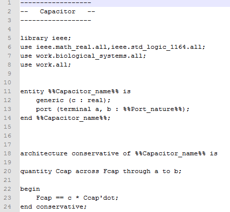
The generation of the different entities (reactions) is made in the same way than the behavioral ones. A synthesis pattern file is presented below:

The filling principle is the same, all the parameters are between “%%” are replaced by the right values.
Other files
But, to perform the conservative simulation, in addition to the entity (reaction) and test-bench files, we have to generate files for each of the species involved. Each species is represented by a set of those electronic elements, and this set is used or not, depending on the type of the reaction. The new files which have to be generated are resistor and capacitor representatives of the different species of the system. We will not going into details in this part because it is a VHDL-AMS specificity. But basically, the set of parameters is different depending if the species are input or output of a reaction. If the species is an input, it is represented just as a resistor. If this species is an output, it is represented by a capacitor and a resistor, as explained in the Models part, but also intermediate mRNA has to be generated, also represented as a resistor and a capacitor. An example of those files is available below:
The architecture of the code stays the same as in the section “How does it work?”.
Test bench
The test bench is generated from a pattern file, with the same manner as the Behavioral test –bench.
Here, to gather the different blocks is less tricky than for the behavioral model. Indeed, the inhibition is not useful for this type of models, so the issue with inhibition is absent. Another reason is the specificity of VHDL-AMS language. In fact, the language has to know the different nodes involved in the system. Each node is a place where more than one signal is connected. Then, the program has to specify each node of the system, and several species can be connected to this node, the gathering of the different blocks is so less difficult here.
Simulation File
The simulation file is the same than the behavioral file.