Team:Groningen/project description
From 2011.igem.org
Project Description
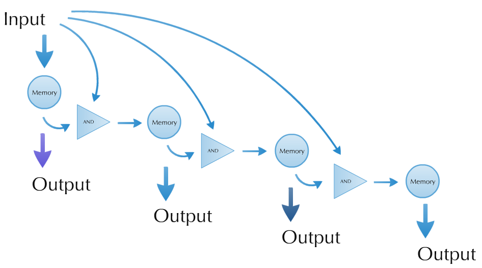
The design of our circuit is described in an abstract way in Figure 1. The first occurrence of the input signal triggers the first memory unit (which consists of an autoinducing loop and a jammer-based off switch) to start. The first memory unit starts triggering the first AND gate. The second occurrence of the input triggers the AND gate. If the first memory unit is running, the AND gate triggers the second memory unit (which also consists of an autoinducing loop and a jammer-based off switch) to start. The second module starts triggering the second AND gate and represses the first module with the use of the jammer-based off switch. This process can be continued, if more autoinducing loops are provided. During operation, the system produces an output which depends on the current running memory unit.
In order to achieve this functionality, we have designed a genetic circuit which is pictured in Figure 2. We have chosen to use the hybB operon promoter as our input signal. This promoter reacts, among other signals, to a cold shock.
The first occurrence of the input signal causes the cell to produce cI-LVA protein (which activates the modified Prm promoter) and taRNA (which has no effect before it degrades). The cI-LVA activates three operons: first, which is an autoinducing loop creating more cI-LVA protein, second which produces fluorescence signal - GFP, and third which produces the crRNA-LasR-LVA transcript. This transcript is self-inhibiting itself.
The second occurence of the input signal produces taRNA again, which now can bind to the crRNA part of the crRNA-LasR-LVA transcript. It activates the transcript and leads to creation of LasR-LVA protein. This protein activates two operons: first which is an autoinducing loop creating more LasR-LVA protein and second which produces fluorescence signal - RFP. The third effect of LasR-LVA protein is shutting down of the first autoinducing loop via a jammer - LasR promoter placed on the anti-sense strand of DNA after the operon.
The system has been divided into three fully functional sub-modules: the cI-based autoinducing loop, the LasR-based autoinducing loop and the taRNA-crRNA-based AND gate. Different variants of those sub-modules will be made and tested. Upon completion, those sub-modules will be combined to create a fully functional system.
 "
"


