Team:Wageningen UR/Project/Devices
From 2011.igem.org
(→Custom fluidic device designed by Team Wageningen UR to measure oscillations) |
|||
| (143 intermediate revisions not shown) | |||
| Line 1: | Line 1: | ||
| - | = | + | <html> |
| + | <head> | ||
| + | <style type="text/css"> | ||
| + | |||
| + | ul li a.currentlinkdevice1 { | ||
| + | color: black !important; | ||
| + | } | ||
| + | |||
| + | ul li a.currentlinktop3 { | ||
| + | color: #63a015 !important; | ||
| + | } | ||
| + | |||
| + | |||
| + | </style> | ||
| + | </head> | ||
| + | <bod> | ||
| + | </body> | ||
| + | </html> | ||
| + | |||
| + | {{:Team:Wageningen_UR/Templates/Header}} | ||
{{:Team:Wageningen_UR/Templates/NavigationTop1}} | {{:Team:Wageningen_UR/Templates/NavigationTop1}} | ||
| - | {{:Team:Wageningen_UR/Templates/ | + | == Custom fluidic device designed by Team Wageningen UR to measure oscillations == |
| + | {{:Team:Wageningen_UR/Templates/NavigationLeftDevice}} | ||
| + | {{:Team:Wageningen_UR/Templates/Style | text= __NOTOC__ | ||
| + | |||
| + | ==== Design ==== | ||
| + | |||
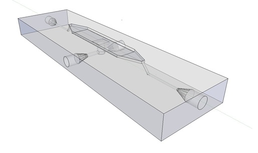
| + | The article [1] we based our oscillatory system on, used microfluidic devices to physically constrain the host cells. This was necessary to induce and monitor oscillatory behavior of a population of ''E. coli''. Such microfluidic devices are very expensive and can only be used once. Therefore we set out to find a cheap alternative for these microfluidic devices. Because a proper alternative was not available we eventually designed our own flow device of which the design is seen in figure 1. For pictures of the device with dimensions click [https://2011.igem.org/Team:Wageningen_UR/Project/DevicesAdditional#Custom_fluidic_device_designed_by_Team_Wageningen_UR_to_measure_oscillations here] or download the Google sketch-up file [http://sourceforge.net/projects/theconstructor/files/ here]. | ||
| + | |||
| + | |||
| + | [[File:mainpic.jpg|center]] | ||
| + | |||
| + | '''Fig.1:''' ''Wireframe model of designed flow device.'' | ||
| + | |||
| + | ===Bacterial growing platforms=== | ||
| + | |||
| + | |||
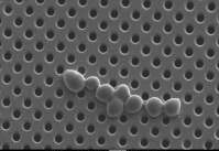
| + | This flow device can currently accommodate two bacterial growing platforms, a microsieve and a microdish. The microsieve - as depicted is figure 2 – consists of a carrier with membrane fragments. These membrame fragments contain evenly distributed pores of 200 nm in diameter. These membranes are used in the dairy industry to sterilize dairy products by removing micro-organisms through filtration. Through filtration a cake of cells will form on the membrane. This potentially gives us a platform capable of inducing and monitoring oscillatory behavior of a population of ''E. coli''. | ||
| + | |||
| + | [[File:microsieve.jpg|center]] | ||
| + | |||
| + | '''Fig.2:''' ''Raster electron microscopy image of the microsieve with Saccharomyces cerevisiae cells.'' | ||
| + | |||
| + | |||
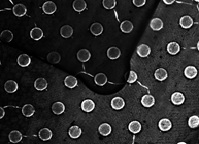
| + | Another bacterial platform is the microdish. The microdish – as depicted in figure 3 – is a thin acrylic layer with pores which is superimposed on a layer of porous aluminum oxide. The wells depicted in figure 3 have a diameter of 180 um and a depth of 40 um. Because the bottom of the wells is porous, nutrients can freely diffuse through the material to any cell contained in the well. These cells will divide until they are physically constrained by the borders of the well. Therefore this is another platform potentially capable of inducing and monitoring oscillatory behavior of a population of ''E. coli''. | ||
| + | |||
| + | |||
| + | [[File:microdish.jpg|center]] | ||
| + | |||
| + | |||
| + | '''Fig.3:''' ''Light microscopy image of the microdish.'' | ||
| + | |||
| + | '''Implementation of both bacterial platforms in the design of the flow device.''' | ||
| + | |||
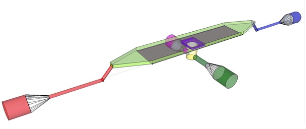
| + | The induction and observation of oscillatory behavior in a population of ''E. coli'' on the microsieve requires a cake of cells to be present on the membrane of the microsieve. In the dairy industry this is achieved by applying the filtrate through an inflow port leading to a chamber, which houses the microsieve. Because an overpressure is produced in the chamber, liquid will be forced through the sieve and the suspended particles – in our case ''E. coli'' cells – will aggregate on the sieve. To prevent that the pressure in the chamber becomes so high that cells get lysed by being pushed through the filter also an outflow port is included. In figure 4 the functional components of the flow device are depicted. | ||
| + | |||
| + | |||
| + | [[File:innerdevice.jpg|center]] | ||
| + | |||
| + | '''Fig.4:''' Functional components of the flow device: In red the inflow port and channel to the top chamber of the flow device. In light green the flow chamber containing either in black the micro-dish or in purple the microsieve. In blue the outflow port of the top chamber. In yellow the bottom chamber with its respective in- and outflow channels and ports.'' | ||
| + | |||
| + | To induce and observe oscillatory behavior in a population of ''E. coli'' in the microdish, nutrients should be readily available for the cells located in the wells. To achieve this, the design - as depicted in figure 4 - implements a second set of inflow (in green) and outflow (in pink) ports. These ports connect to the lower chamber (yellow) and are used to flow a fresh supply of medium through the lower chamber. When the lower chamber is filled with medium, the medium can diffuse through the pores in the aluminum oxide hereby constantly giving the cells access to fresh medium. These ports connect to a chamber (yellow) come in contact with the aluminum oxide microdish (in black) when filled with medium. Through the addition of these ports a continuous supply of fresh medium is supplied. | ||
| + | |||
| + | ===General design considerations.=== | ||
| + | |||
| + | Because we want to use the flow device in combination with fluorescence microscopy the distance between the objective and the sample is crucial. Therefore we choose for a top chamber depth of 1 mm because in combination with the deckled of 1 mm, this distance is short enough for the focusing depth of the 20 x objective of the microscope. Furthermore this also reduces the volume of the chamber, reducing overhead liquid which could contain precious reactants, such as acyl-homoserine-lactone (AHL). | ||
| + | |||
| + | |||
| + | ===The Result.=== | ||
| + | |||
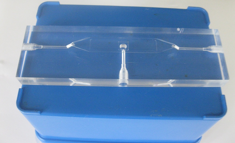
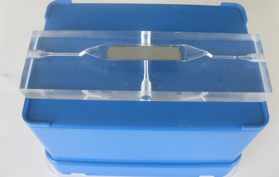
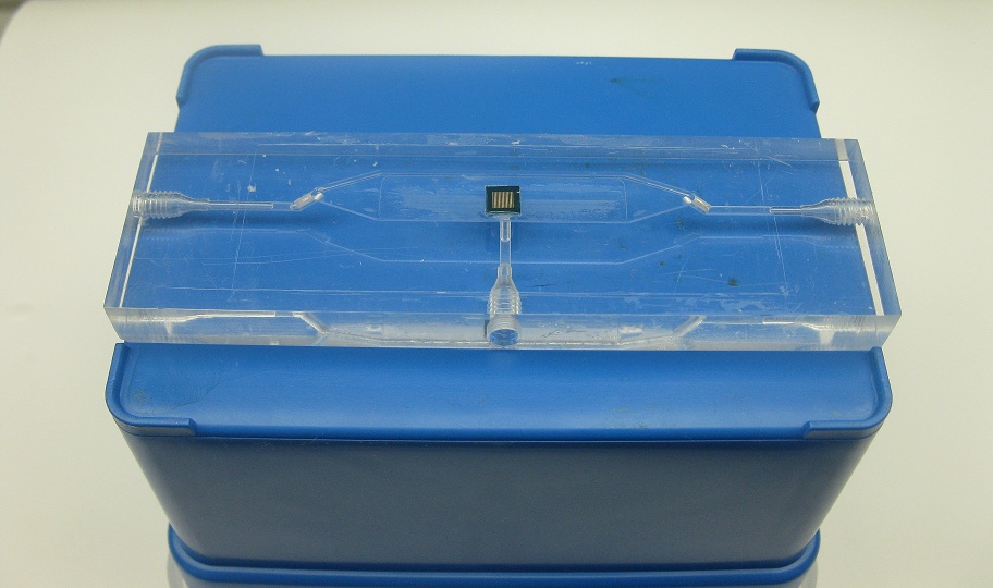
| + | In the following pictures our flow device is depicted. In figure 5, the device is seen without any of the bacterial growing platforms installed. In figure 6, the flow device is seen with a microdish installed in the appropiate socket, depicted in black in figure 4. In figure 7, the flow device is seen with a microsieve installed in the appropiate socket, depicted in purple in figure 4. | ||
| + | |||
| + | |||
| + | [[File:without2.jpg|250px]] [[File:devicedish4.jpg|240px]] [[File:devicesieve2.jpg|260px]] | ||
| + | '''Fig.4''' ''Flow device (left) with microdish (middle) and microsieve (right)'' | ||
| + | |||
| + | |||
| + | |||
| + | [[Team:Wageningen_UR/Project/Devices#Design| back to top]] | ||
| + | |||
| + | |||
| + | '''Links and references:''' | ||
| + | |||
| + | [1][http://www.nature.com/nature/journal/v463/n7279/abs/nature08753.html Danino et al. 2010] | ||
| + | |||
| + | |||
| + | |||
| + | |||
| + | |||
| + | |||
| + | |||
| + | |||
| + | |||
| - | |||
| - | |||
| - | |||
| - | |||
| - | |||
| - | + | }} | |
| - | + | ||
Latest revision as of 03:18, 22 September 2011
 "
"


