Team:Wageningen UR/Project/DevicesAdditional
From 2011.igem.org
Matthijnwur (Talk | contribs) (Created page with "File:chamber.jpg File:corner.jpg File:inside 6.jpg File:inside 7.jpg") |
Matthijnwur (Talk | contribs) (→Custom fluidic device designed by Team Wageningen UR to measure oscillations) |
||
| (4 intermediate revisions not shown) | |||
| Line 1: | Line 1: | ||
| - | + | <html> | |
| + | <head> | ||
| + | <style type="text/css"> | ||
| - | + | ul li a.currentlinkdevice1 { | |
| + | color: black !important; | ||
| + | } | ||
| - | + | ul li a.currentlinktop3 { | |
| + | color: #63a015 !important; | ||
| + | } | ||
| - | [[File:inside 7.jpg| | + | |
| + | </style> | ||
| + | </head> | ||
| + | <bod> | ||
| + | </body> | ||
| + | </html> | ||
| + | |||
| + | {{:Team:Wageningen_UR/Templates/Header}} | ||
| + | {{:Team:Wageningen_UR/Templates/NavigationTop1}} | ||
| + | == Custom fluidic device designed by Team Wageningen UR to measure oscillations == | ||
| + | {{:Team:Wageningen_UR/Templates/NavigationLeftDevice}} | ||
| + | {{:Team:Wageningen_UR/Templates/Style | text= __NOTOC__ | ||
| + | |||
| + | |||
| + | |||
| + | |||
| + | |||
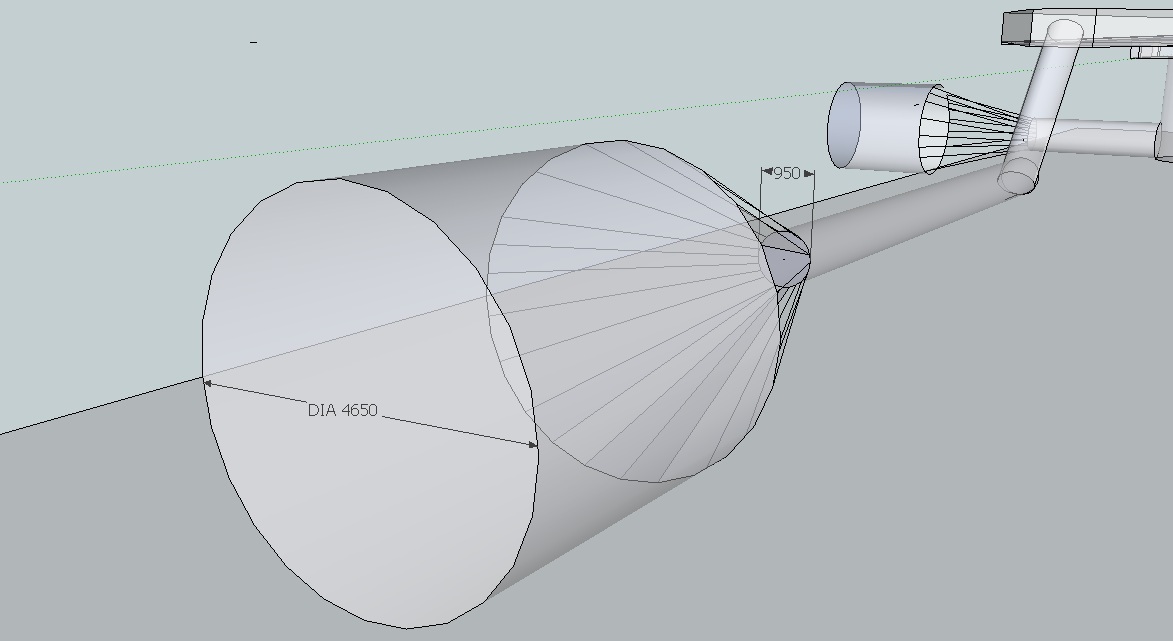
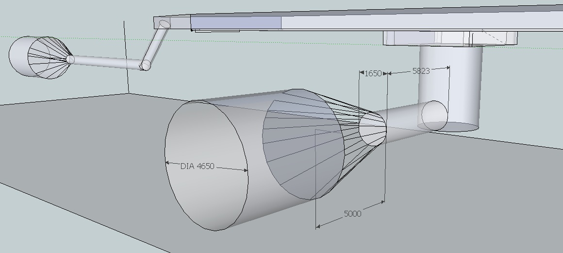
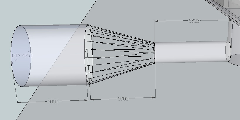
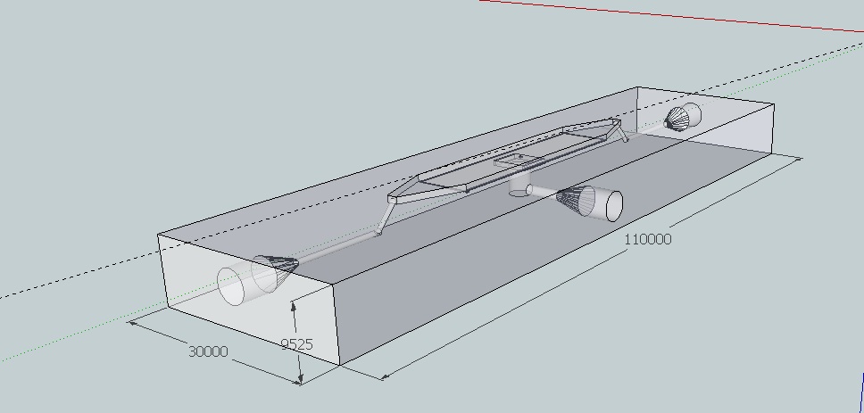
| + | The following pictures depict the dimensions of the flow device and it,s functional components in micro meters. These pictures dont include the outflow port of the bottom chamber, the dimensions of this port are the same as the inflow port of the bottom chamber. For an up to date google sketch-up file of the final design click [http://sourceforge.net/projects/theconstructor/files/ here]. | ||
| + | |||
| + | |||
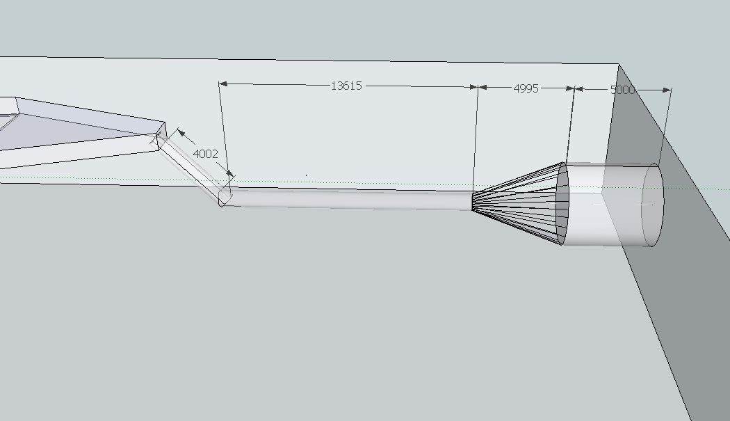
| + | [[File:chamber.jpg|770px|]] | ||
| + | |||
| + | Dimensions flow chamber. | ||
| + | |||
| + | |||
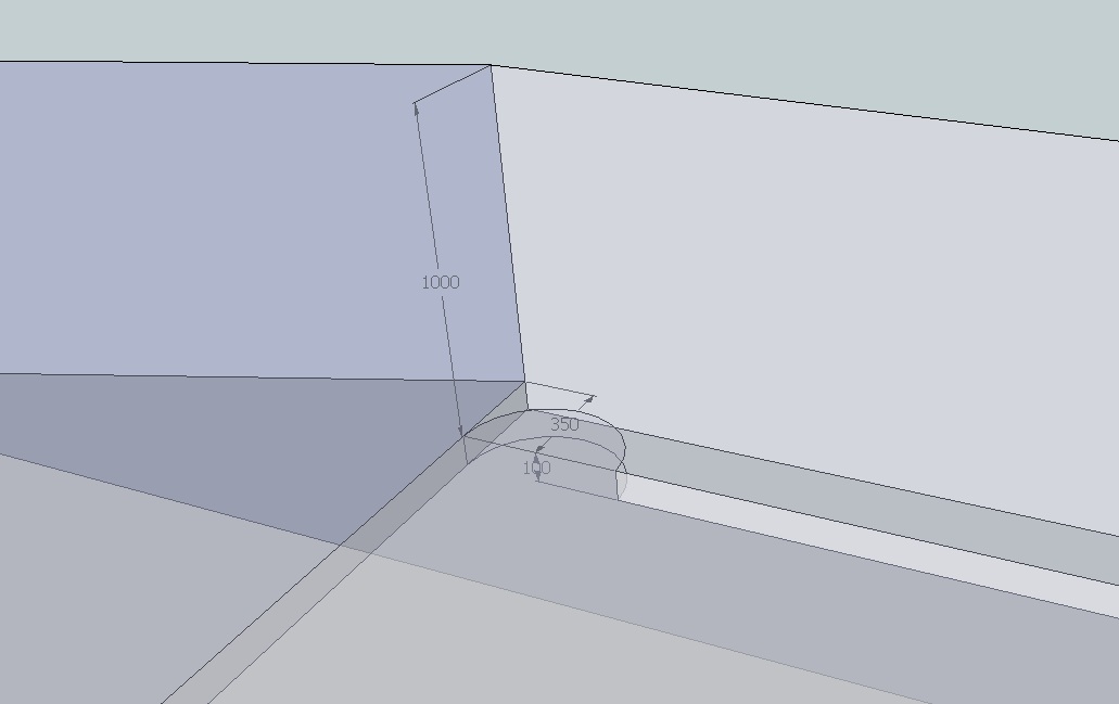
| + | [[File:corner.jpg|770px|]] | ||
| + | |||
| + | Height bottom chamber and dimensions of the nodge which is necessary for having the mico-dish square in the chamber. | ||
| + | |||
| + | |||
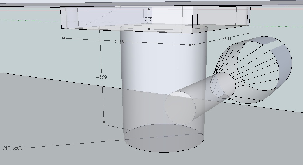
| + | [[File:inside 6.jpg|770px|]] | ||
| + | |||
| + | Dimensions of the bottom chamber and micro-sieve socket. | ||
| + | |||
| + | |||
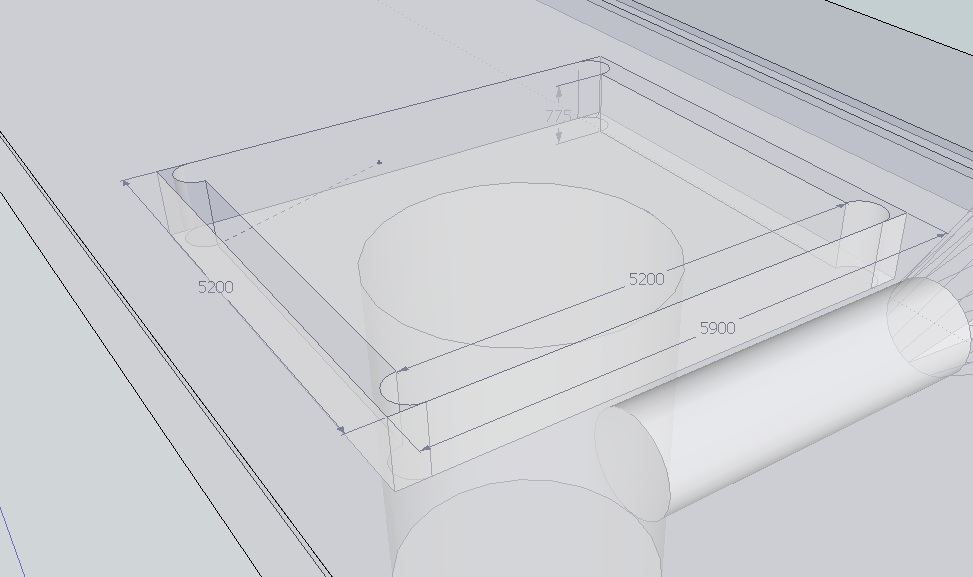
| + | [[File:inside 7.jpg|770px|]] | ||
| + | |||
| + | Dimensions of micro-sieve socket from top. Nodges have the same function and dimensions as the nodge of the micro-dish. | ||
| + | |||
| + | |||
| + | [[File:inside.jpg|770px|]] | ||
| + | |||
| + | Dimensions of outflow channel and port of top chamber. | ||
| + | |||
| + | |||
| + | |||
| + | [[File:inside2.jpg|770px|]] | ||
| + | |||
| + | Radius of ports,in and out flow channel. | ||
| + | |||
| + | |||
| + | [[File:inside3.jpg|770px|]] | ||
| + | |||
| + | Radius of flowthrough channel and port. | ||
| + | |||
| + | |||
| + | [[File:inside4.jpg|770px|]] | ||
| + | |||
| + | Dimensions of flowthrough channel and port. | ||
| + | |||
| + | |||
| + | [[File:outsidedimensions.jpg|770px|]] | ||
| + | |||
| + | Outside dimensions of flow device. | ||
| + | |||
| + | }} | ||
Latest revision as of 13:01, 20 September 2011
 "
"


