Team:Wageningen UR/Project/Devices
From 2011.igem.org
(→Main Project) |
(→Main Project) |
||
| Line 28: | Line 28: | ||
{{:Team:Wageningen_UR/Templates/Style | text= __NOTOC__ | {{:Team:Wageningen_UR/Templates/Style | text= __NOTOC__ | ||
=== Devices === | === Devices === | ||
| + | =====Microfluidic devices===== | ||
| + | The platform best suited for these requirements is a microfluidic device, such as the one used by Danino & Hasty. However, such devices need to be custom designed and are prohibitively expensive. Because the design contains cell traps (ca. 100x50x2μm) the devices are difficult to clean, and it is likely that each device could be used only once. The underlying virtue of using a micro fluidic device is that it is a container that allows high enough cell densities for achieving threshold AHL levels while allowing cell density to remain constant independent of medium flow rate. | ||
| + | However, there exist a few alternatives that might fulfil the necessary requirements to serve as a platform for detecting oscillations. Some other alternatives besides the one already suggested, could be a standard microfluidic device (as opposed to a custom one) as offered by microliquid, these have a price around 150 euro’s a piece. This device consists of a linear channel which has an inflow and an outflow port. Danino & Hasty employed a similar design in his research of the propagation of the GFP signal. However, the dimensions of standard device are larger than the custom platform the micro-traps. Probably, this means that diffusion of the AHL will increase dramatically, slowing down oscillation periods. On the other hand, this device does not physically trap the cells the same way as the custom device. In this device the cells are trapped between the walls of the device locking them in place. These micro fluidic devices could be reusable. | ||
| + | |||
| + | =====Small Chemostat===== | ||
| + | A second alternative might be a small chemostat. One of the benefits of using a chemostat is that it is continuously stirred, and thus AHL levels are the same throughout the culture. Therefore the system is not dependent on AHL diffusion. Due to the nature of a chemo-stat there is a continuous out-flow of cells, which might be problematic for reaching sufficient cell densities, and which can produce high enough levels of AHL. One way of solving this could be to use a system in which cells are retained in the system via the means of membranes. Another alternative might be at the molecular level, wildtype LuxR is activated when AHL concentrations reach ~100 nM. In the registry of standard biological parts a mutant LuxR(BBa_I729004) is available, which is activated at a concentration of 10nM. Thus this mutant LuxR can in theory reduce cell densities 10 fold, but still allow a functioning system. | ||
| + | |||
| + | =====Microsieve===== | ||
| + | However, the most viable alternative to the microfluidic device might be a microsieve. This device also traps cells just like a microfluidic device. However the mechanism of entrapment is different: a microfluidic device traps cells in a physical trap, while microsieves do this by applying an overpressure. Through this overpressure cells are retained on the sieve. By varying the overpressure the thickness of the “cake” of cells can be varied. Furthermore these sieves are chemically inert and can withstand harsh chemical and physical circumstances, meaning that they can be cleaned and reused again. | ||
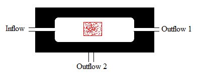
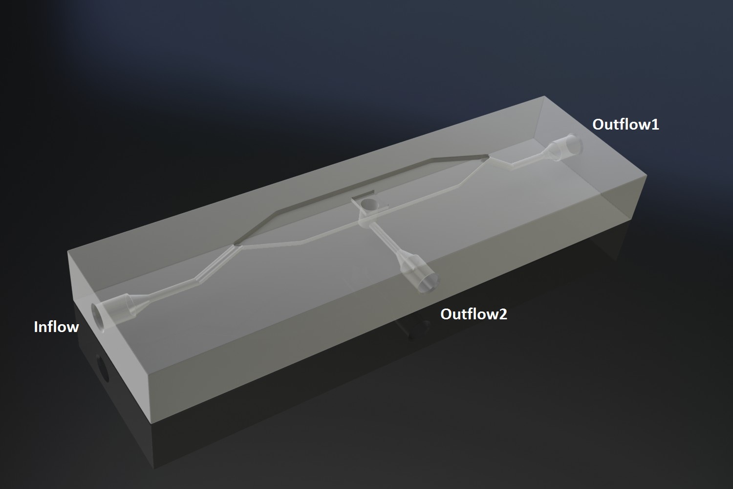
| + | The device consists of a microsieve contained in a flow chamber. The microsieve is made of silicon and contains pores as small as 200 nm. Because the sieve is made out of silicon it is chemically inert and can easily be cleaned and reused. The flow chamber has an inflow and two outflow ports. Through the inflow port a liquid enters containing suspended particles. When the liquid passes the micro sieve it will encounters negative pressure whereby particles are trapped by the sieve. As particles accumulated, they eventually form a “cake”. The filtered liquid leaves the device via the outflow port below the sieve, and remaining liquid in the chamber leaves the device via the outflow port 1. | ||
| + | |||
| + | |||
| + | [[File:mainproject09.png]] | ||
| + | |||
| + | '''Fig.10.''' ''Schematic of a micro-filtration device. The microsieve is 5x5mm.'' | ||
| + | |||
| + | |||
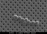
| + | [[File:mainproject10.png]] | ||
| + | |||
| + | '''Fig.11.''' ''Photograph of cells growing on a microsieve.'' | ||
| + | |||
| + | |||
| + | This device is particularly promising for a few reasons. Through the negative pressure a small pore size filter is able to be seeded with micro-organisms that will grow on its surface, as depicted in Figure 11. Once these micro-organisms are trapped and growth medium is supplied as inflow, they will start to divide and form a tight layer on the sieve. | ||
| + | Furthermore by adjusting the flow rate or filter pore size and porosity the cell layer can be varied of thickness. This could be necessary for reaching the correct balance between AHL production and removal. Another reason why this device is promising is because of its low price. The company Aqua Marijn, which is partly located at the departed of organic chemistry can produce custom versions of the chamber and supply the micro filter for around 50 euros per device. Preliminary discussions with representatives have proven to be promising. | ||
| + | |||
[[File:Module-2 WUR.JPG|400px]] | [[File:Module-2 WUR.JPG|400px]] | ||
Revision as of 20:12, 13 September 2011
 "
"


