Team:EPF-Lausanne/Tools/Microfluidics/HowTo2
From 2011.igem.org
(→Hooking it all up: preparing tubes and priming the chip) |
|||
| Line 5: | Line 5: | ||
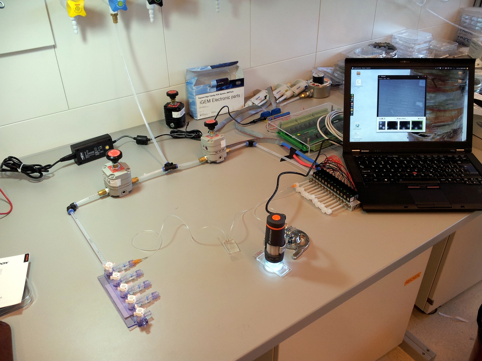
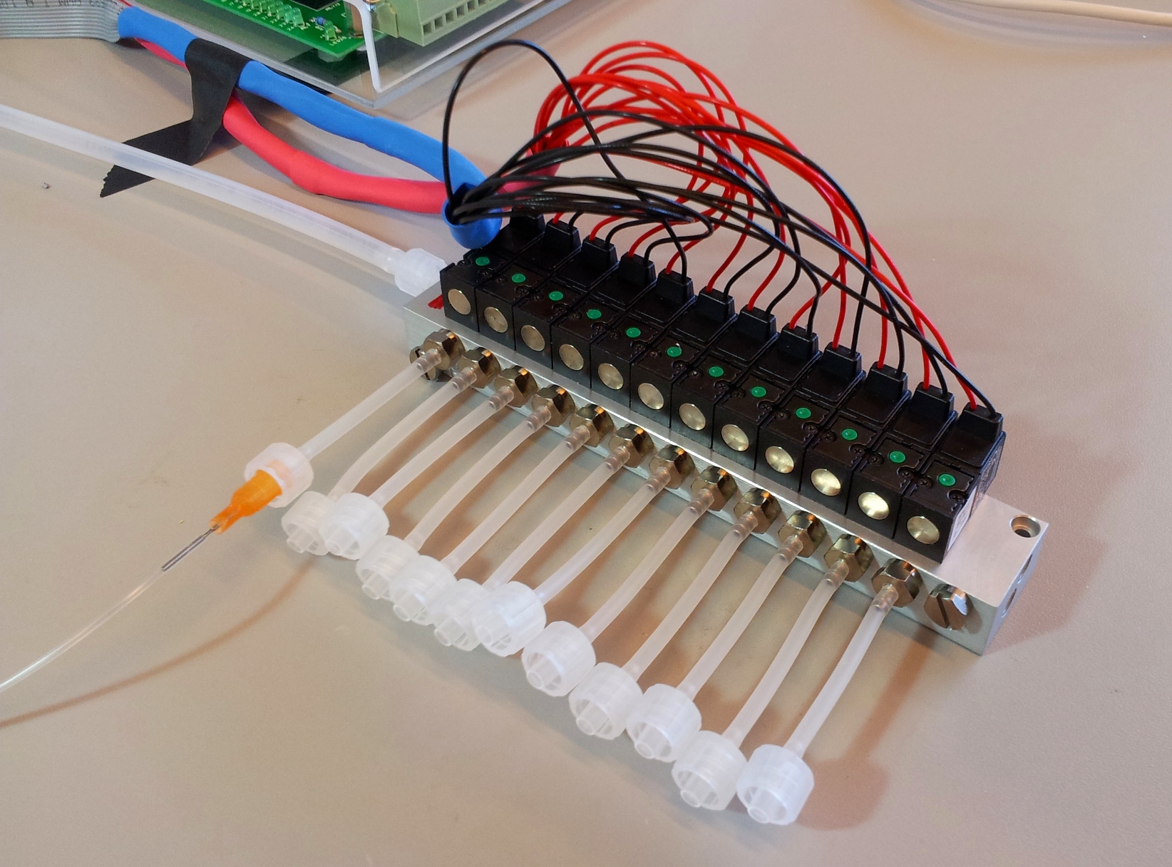
[[File:EPFL-Basic-setup.jpg|thumb|right|300px|A basic computer-controlled microfluidics setup. Note the compressed air input split into two sides, both fed through a pressure regulator. The left side is the low-pressure manifold for the flow layer. The right side is the high-pressure solenoid array for the control layer.]] | [[File:EPFL-Basic-setup.jpg|thumb|right|300px|A basic computer-controlled microfluidics setup. Note the compressed air input split into two sides, both fed through a pressure regulator. The left side is the low-pressure manifold for the flow layer. The right side is the high-pressure solenoid array for the control layer.]] | ||
| - | + | Microfludic chips are nothing but a piece of moulded rubber. To actually get use them, an external setup of tubing, compressed air, and valves is needed to flow in fluids and actuate the on-chip valves. To see what's happening, you'll also need some form of microscope. No matter the application of the chip, whether it is designed to study fluid mechanics, to characterise protein-DNA interaction, or even cultivate bacteria and nematodes, the external setup remains essentially the same. | |
== Making a chip == | == Making a chip == | ||
Revision as of 08:12, 19 September 2011
Microfluidics how-to
Microfluidics Main | How-To Part I | How-To Part II | TamagotchipTo be done: describe how to design and make a chip. Or how to order one.
Microfludic chips are nothing but a piece of moulded rubber. To actually get use them, an external setup of tubing, compressed air, and valves is needed to flow in fluids and actuate the on-chip valves. To see what's happening, you'll also need some form of microscope. No matter the application of the chip, whether it is designed to study fluid mechanics, to characterise protein-DNA interaction, or even cultivate bacteria and nematodes, the external setup remains essentially the same.
Contents |
Making a chip
TODO: outline wafer fabrication and chip fab. Or just refer to Stanford chip ordering service.
A basic microfluidics control setup
Injecting fluids: mains pressure and tubing, pressure regulators
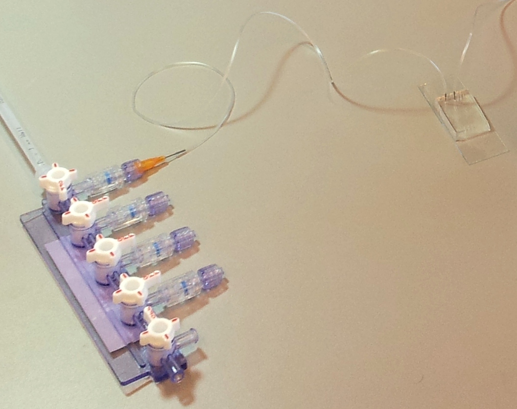
A microfluidic chip is a network of small channels for fluids. To inject fluid in, a small (.02" inner diameter) tube is filled, then plugged into the chip through one of the punched holes (connecting them with a tubular metal pin). On the other end, the tubes are plugged into a manifold, in turn supplied with air at about 0.2 bar (3 psi), as set by a pressure regulator. The fluid is thus forced into the channels by the compressed air. A syringe can also be used to fill the chip, but it is hard to keep an even pressure (plus you quickly run out of hands).
Controlling flow: microfluidic valves and 3-way valves.
Our chips have a second control layer above or below the main flow layer. The layers are separated by a thin membrane of PDMS, and their channels overlap in specific locations. When channels of the control layer are pressurized, the membrane bends into the flow layer and blocks it. This creates a microfluidic 'on-chip' valve.
The channels of the control layer are filled in the same way as the flow layer, but require much higher pressure to bend the membrane. We typically used about 2 bar or 30 psi. Each independant valve in the control layer is pressurised by a different tube, regulated by a three-way valve. These switch between high pressure (from mains pressure, and the pressure regulator) to low pressure (atmospheric pressure), and hence allow quick toggling of the microfluidic valve between the open (unpressurised) and closed (pressurised) state. Three way valves come in manually- or electrically-controlled flavours. The manual kind is simpler and more reliable; we use them for the MITOMI chips. The electric kind (more specifically solenoid valves) we use for the web-controlled setup.
Watching what's going on: the microscope
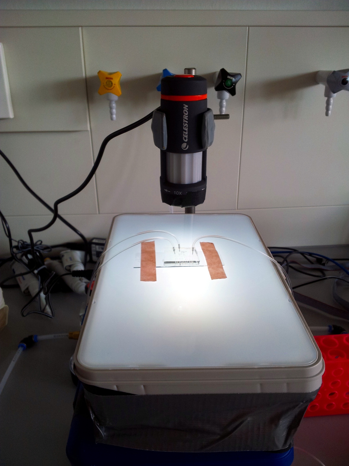
In our experience, the best tool to look at a microfluidic chip is a low-magnification rear-illuminated binocular microscope. However, we needed a cheap way of viewing the chip on a computer, to then stream the image through internet. We used a toy webcam microscope ($50), and bought a toy light table for rear-illumination ($25). To improve stability and focusing, we fixed the microscope to a chemist's stand and placed the light table on a scissor jack.
- Webcam microscope: Celestron Deluxe Handheld Digital Microscope
- Light table: Artograph GLOBOX
Hooking it all up: preparing tubes and priming the chip
The presence of bubbles in a channel increases its fluidic resistance, and therefore perturbates or even blocks flow. To avoid this, the first step in running a chip is priming: filling all the channels with fluid, then closing all the micro-valves and keeping pressure applied, until any air remaining in the chip diffuses through the chip walls and disappears.
Once all the channels are filled, the experiments can be ran. For the worm chip, we would prime it with buffer, then introduce the worm when the chip is filled. For the MITOMI chip, we would flow in proteins and whatever.
 "
"


