Team:EPF-Lausanne/Tools/Microfluidics/HowTo2
From 2011.igem.org
| Line 18: | Line 18: | ||
On the other end, the tubes are plugged into a manifold, in turn supplied with air at about 0.2 bar (3 psi), as set by a pressure regulator. The fluid is thus forced into the channels by the compressed air. A syringe can also be used to fill the chip, but it is hard to keep an even pressure (plus you quickly run out of hands). | On the other end, the tubes are plugged into a manifold, in turn supplied with air at about 0.2 bar (3 psi), as set by a pressure regulator. The fluid is thus forced into the channels by the compressed air. A syringe can also be used to fill the chip, but it is hard to keep an even pressure (plus you quickly run out of hands). | ||
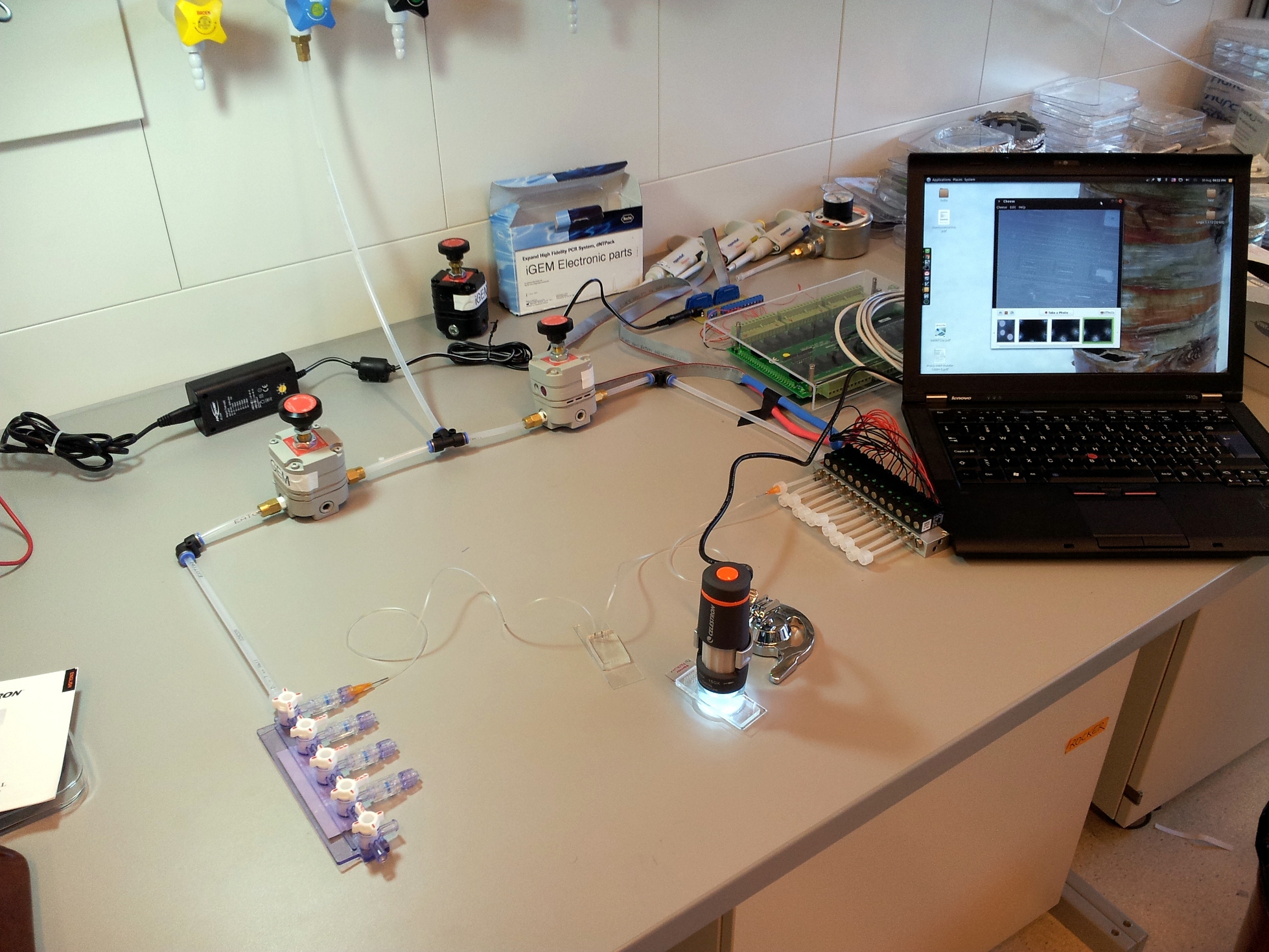
| - | [[File:EPFL-Basic-setup.jpg|thumb| | + | [[File:EPFL-Basic-setup.jpg|thumb|left|A basic computer-controlled microfluidics setup. Note the compressed air input split into two sides, both fed through a pressure regulator. The left side is the low-pressure manifold for the flow layer. The right side is the high-pressure solenoid array for the control layer.]] |
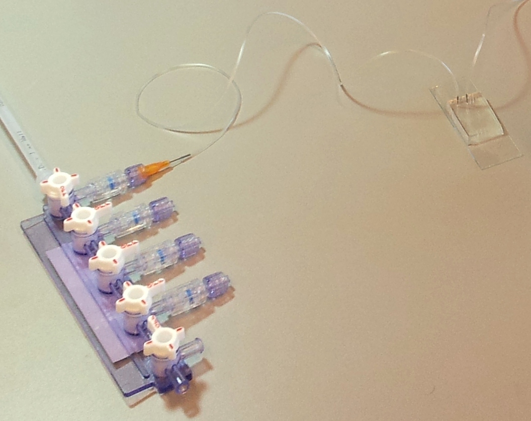
| - | [[File:EPFL-Flow-manifold.jpg|thumb| | + | [[File:EPFL-Flow-manifold.jpg|thumb|left|Close-up of the flow-layer tube: connected to a manifold, and plugged into the chip using a tubular pin]] |
{{:Team:EPF-Lausanne/Templates/Footer}} | {{:Team:EPF-Lausanne/Templates/Footer}} | ||
Revision as of 18:41, 18 September 2011
Microfluidics how-to
To be done: describe how to design and make a chip. Or how to order one.
Microfludics chips are nothing but a piece of moulded rubber. To actually get anything out of them, an external setup of tubing, compressed air, and valves is needed to flow in fluids and actuate the on-chip valves. To see what's happening, you'll also need some form of microscope.
Making a chip
A basic microfluidics control setup
Injecting fluids: mains pressure and tubing, pressure regulators
A microfluidic chip is a network of small channels for fluids. To inject fluid in, a small (.02" inner diameter) tube is filled, then plugged into the chip through one of the punched holes (connecting them with a tubular metal pin). On the other end, the tubes are plugged into a manifold, in turn supplied with air at about 0.2 bar (3 psi), as set by a pressure regulator. The fluid is thus forced into the channels by the compressed air. A syringe can also be used to fill the chip, but it is hard to keep an even pressure (plus you quickly run out of hands).
 "
"

