"
"
Team:Cornell/Results
From 2011.igem.org


Results |
Protocol |
Notebook |
Parts Submitted

Contents |
Results Summary
- Two of the main components of our project are as follows:
- AviTagged enzymes that modify a substrate according to a biosynthetic pathway
- Avidin coated microfluidic channels which bind AviTagged proteins
- We decided to test these components separately before we conducted a final biomodification test. Below are the tests we conducted:
- The modified enzymes:
- Are our modified enzymes synthesized by the bacterial cells?
- Do our modified enzymes modify our substrate in a non-microfluidic setting?
- The microfluidic device :
- Will biotinylated fluorescent probes attach to NeutrAvidin coated walls of the microfluidic device?
- How long will biotinylated substances stay attached to the microfluidic device under continuous flow?
- Will cell lysate have an effect on the binding efficiency of our biotinylated proteins?
- Will biotinylated GFP bind to our microfluidic device?
- Final bio-modification test: Will biotinylated enzymes bound to a microfluidic device modify our substrate?
- From these experiments we were able to extrapolate various results.

1) Modified Enzymes
1a) Western Blot
Goal - to determine if our AviTagged enzymes are synthesized.
Experiment
- Negative Control - cellular lysate containing non-AviTagged proteins.
- Test - Run a standard western blot procedure using AviTagged VioA, VioB, VioE and GFP.
Results
- Bands were observed at expected locations for VioA, VioE and GFP.

1b) Functionality of biotinylated enzymes
Through the summer, we successfully constructed the tagged violacein pathway enzymes VioA, VioB, and VioE and submitted those parts to the registry. These three enzymes in series are capable of converting L-tryptophan into prodeoxyviolacein, a dark green colored intermediate of the violacein pathway. Each enzyme sequence was constructed to have the AviTag sequence included on its C-terminus, followed by the stop codon so that one single fusion protein is expressed. The AviTag is capable of biotinylating the enzymes so that they can be bound to surfaces using a simple NeutrAvidin ligand system.
To simplify the construction process, each enzyme sequence was PCR'd off the iGEM Distribution sample with a KpnI site followed by the iGEM prefix, the gene of interest, and ended with an SphI or HindIII site that replaced the location of the stop codon. These PCR products could then be ligated into a modified pZE12-SMCS backbone which contained the AviTag sequence followed by the stop codon, iGEM suffix and ClaI site. This backbone was constructed using the primer insert method outlined in the Project Description.
With the modified enzymes, we performed experiments to show their expression and utilization of tryptophan using a UV/Vis spectrometer at the peak wavelengths at which tryptophan responds to (590,638, and 562 nm). The OD measurements of solutions contain equivolume of VioA, VioB, 40 mM Hydrogen Peroxide (for oxidation of tryptophan) and VioE lysate with varying concentration of tryptophan. The results are shown below.

The green points represent readings at 562 nm, blue at 590 nm, and red at 638 nm at 0.008 g/mL concentration of L-Tryptophan and 40 mM H202. As you can see, the absorbance of tryptophan noticeably decreases over a time course of 1 hour. This experiment was recreated varying the ratio of enzymes and concentration of initial tryptophan. The results showed a similar decreasing trend.

This is the control tryptophan readings. In the absence of violacein enzymes, the amount of tryptophan showed the opposite trend.
Peak wavelength values were found with the following reference
Sánchez, C Reevaluation of the violacein biosynthetic pathway and its relationship to indolocarbazole biosynthesis. Chembiochem : a European journal of chemical biology Vol. 7, 8, 2006, p. 1231
2) Microfluidic Device
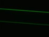
2a) Binding Experiment
Goal - to determine if the biotinylated enzymes would attach to the NeutrAvidin coated wall.
Experiment
- Negative Control - chip that is not coated with NeutrAvidin through which we flowed ATTO 590.
- Test - NeutrAvidin coated chip through which we flowed ATTO 590.
- Flow Rate - 5 µL/min
- Run Time - 20 min
- After the experiment, air was flown through the chips and pictures were taken.
Results
- The red fluorescence indicates that the enzyme successfully bound to the channel wall.
Control Test


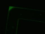
2b) Lysate Experiment
Goal - to determine the effect lysate would have on the binding efficiency between the NeutrAvidin coated walls and the biotinylated enzymes.
Experiment
- Positive Control - NeutrAvidin coated chip through which we flowed ATTO 520
- Negative Control - uncoated chip through which we flowed ATTO 520
- Test - NeutrAvidin coated chip through which we flowed a 5:1 ratio of lysate to ATTO 520.
- Flow Rate = 5 µL/min
- Total Run Time = 30 min
- Entire setup was covered in aluminum foil and the lights were dimmed.
After the experiment, air was flown through the chips and pictures were taken. Channels were filled with deionized water and stored in the 4 degree fridge wrapped in aluminum foil.
Results
- The test chip showed a lower level of fluorescence compared to the positive control chip. This indicates that lysate has a small inhibitory effect on the binding between NeutrAvidin and biotin.
Negative Control Positive Control Test


2c) Continuous Flow Experiment
Goal - to determine how long the attached enzymes would stay attached under continuous flow.
- Negative Control - noncoated chip
- Test - Flow DI water through a chip with ATTO 520 attached to the NeutrAvidin coated PDMS for 15min.
- Flow Rate = 200 µL/min
- Total Run Time = 45 min (three 15 min intervals)
- After each interval, the chip was washed with air and a picture was taken in air.
Results
- The pictures indicate that the fluorescence gradually decreases under continuous flow. This suggests that the chips might have to be recoated after extended wear.
Control After 15 min After 30 min After 45 min


2d) GFP BioBrick
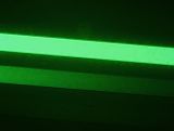
Goal - to determine if our AviTagged GFP will bind to our NeutrAvidin-coated chip.
Experiment
- Negative Control - A coated chip that is flushed with deionized Water
- Test - A chip coated with NeutrAvidin with filtered GFP lysate flown through
- Flow Rate - 5 µL/min
- Total Run Time - 20 min
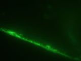
- The GFP containing cells were lysed with BugBuster and filtered through a PD-10 Desalting Columns to remove excess biotin. Afterwards the chip was stored in deionized water in the fridge in aluminum foil. 4 days later we took the chip out and imaged it again. Then deionized water was flushed through and the chip was reimaged. It was seen that most of the binding occurred at the inlet port and the first channel. By the second channel, no fluorescence was detected.
Results
- The presence of green fluorescence shows that our BioBrick successfully bound to the channel wall. Furthermore, green fluorescence was still present even after the chip was stored for 4 days in the fridge. However, the fluorescence after 4 days was significantly less than the initial fluorescence.
Control Initial Test (in water) After 4 Days

3) Final Invitro Bio-modification Test
Goal - to determine if prodeoxyviolacein can be produced in our cell free system.

Experiment
- Negative Control - 3 coated chips (blank chips) with tryptophan flushed through
- Control 1 - VioA chip, VioB chip and a Blank chip
- Control 2 - VioA chip and Blank chip ::*Test - VioA chip, VioB chip and VioE chip
- Flow Rate - 5 µL/min
- Total Run Time - 6 hours
- Enzymes were incubated in the chips for 1 hour with no flow. The enzyme solution was then replace with fresh enzyme solution and incubated again for 1 hr. The constructed enzyme-immobilized chips were then connected in series such that a solution containing tryptophan substrate would flow through each chip in the order of the pathway. Dissolved solution of 0.04 g/ml tryptophan and 0.040 mM H2O2 at a pH of 9.0 was flown in a continuous flow reaction at 5 µl/min. The enzymatic pathway is flow path is VioA VioB VioE into prodeoxyviolacein. 1 ml samples were collected after 6 hours of continuous flow.
Results
The Results show that the tryptophan solution undergoes at least 2 chemical reactions due to the formation of a colored product after the VioA chip and the removal of that color after the VioE chip. The solution after the VioB chip exhibited the same coloration as the collected samples after VioA. Further chemical testing will be done the week of October 31st to do HPLC confirmation of prodeoxyviolacein formation.
The positive western blots prove the presence of biotinyalted VioA and VioE which should have similar binding efficiency to the GFP binding experiment. Initial western blot did not confirm the presence of VioB, most likely due to its size. However, the 1 Liter VioB culture prepared for this experiment exhibited a deep red color, unique among the prepared cultures which signifies the presence of a non-native chemical reaction which we believe to be active VioB enzyme.

Light-Induced Lysis
We designed the light-induced apoptosis system using APE and submitted the part to Invitrogen Life Technologies for synthesis. Given our final construct was in excess of 6,000 bp, synthesis is currently being performed into two subsections. The first of which is the light sensitive promoter (Pcpcg2) followed by the lysis cassette and the genes necessary for the biosynthesis of phycobilins. The second component was the CCaS and CCaR. CCaS is the surface 532 nm green light activated protein which phosphorylates, and activates, CCaR to bind to the light sensitive promoter and express the downstream gene.
So far, we have received the second component of our light system, and we have BioBricked this part for submission and use with the international parts registry. Please see this page for more information.
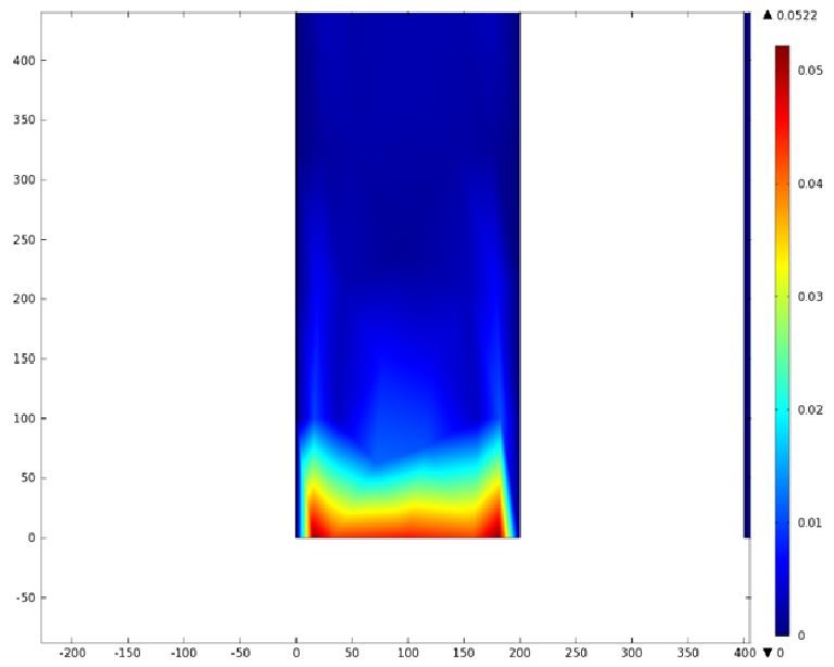
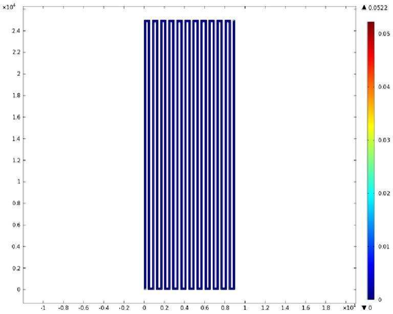
Mathematical Modeling
Using the Comsol Multiphysic software we created a velocity profile for our microfluidic device.
Velocity Profile of the Entire Chip (m/s)
 '''Velocity Profile of the Inlet (m/s)'''