Complete Project Description
Introduction
The aim of this project is to design and implement a system exhibiting sustained oscillatory protein expression which should be visible and synchronized on the scale of a physically constrained population of E. coli cells. The principles that govern this type of behaviour have been studied both in theory and in practice, and as such there exists a solid foundation to apply these ideas in the context of the iGEM competition. In essence, this project consists of constructing a plasmid containing genes, the products of which reciprocally affect each other’s expression in a reliable manner. Based on a previously established design, we intend to take advantage of the great variety of standardized, interchangeable and freely available BioBrick Parts (genes and regulatory elements; REF the iGEM website and the [http://partsregistry.org/Main_Page Registry of Standard Biological Parts]) to construct modified genetic circuits, aiming at an improved bacterial oscillator. Due to the difficulty in experimentally verifying the phenomena we wish to observe, special considerations regarding the experimental set-up will have to be made.
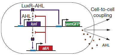
The starting point for the genetic circuitry we intend to make is a design recently published in the article “a synchronized quorum of genetic clocks” by Danino & Hasty (REF the [http://www.nature.com/nature/journal/v463/n7279/abs/nature08753.html article “a synchronized quorum of genetic clocks”]). This genetic circuit uses natural elements of bacterial quorum sensing systems to form coupled positive and negative feedback loops which control the expression of a reporter protein: the LuxI enzyme that catalyses the last step of the acyl-homoserine lactone (AHL) biosynthesis, the AHL-responsive transcriptional regulator LuxR, and the reporter Green Fluorescent Protein (GFP) (Figure 1). The AHL molecules can easily diffuse through cell membranes to the extracellular medium. This allows all the cells in a culture to influence each other’s activity in a uniform manner (quorum sensing). The result being that the oscillations arising from the genetic feedback loops are synchronized on the scale of a whole cell culture. All of the parts used in this design exist in the Registry of Standard Biological Parts and are freely available for our use.
Fig.1. What synchronized oscillation of Green Fluorescent Protein in E. coli cells might look like.
Mechanism
There are a number of genetic circuit topologies that have the potential to exhibit oscillatory behaviour under certain conditions. One simple design is the Smolen Oscillator which consists of two genes connected through double feedback loops. The mechanism we intend to construct consists of components of the lux quorum sensing system that are configured in such a way.
Fig.2. Basic oscillating genetic circuit as published by Danino & Hasty.
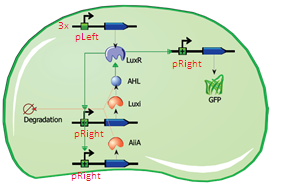
The main elements that comprise this circuit are the genes LuxI, LuxR, AiiA, GFP, and the promoters that regulate their activity. LuxI encodes the enzyme LuxI which enzymatically produces the molecule acyl-homoserine lactone (AHL). When AHL is bound to the transcription factor LuxR, it becomes active and induces transcription from the LuxI promoter (which normally has very low basal expression). Subsequently, AiiA is expressed and negatively regulates the pRight promoter by catalysing the degradation of AHL. The feedback loop emerging from this configuration results in periodic oscillatory protein expression. AHL is soluble and can freely diffuse through the cell membrane into extracellular medium and into other cells, effectively normalizing the AHL concentration across an entire localized cell culture, which is how synchronization can occur. Placing the gene for a reporter molecule, such as Green Fluorescent Protein or Luciferase, under a copy the LuxI promoter allows the dynamics of protein expression to be monitored.
Designs
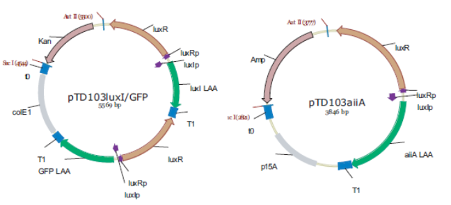
In the original design, Danino & Hasty placed the genes LuxI (from V. fischeri), AiiA (from B. Thurigensis) and yemGFP genes under the control of three identical copies of the natural Lux promoters of V. fischerii. This promoter region actually consists of two promoters regulating transcription in opposite directions. To avoid complications resulting from this, the authors placed a copy of the LuxR gene behind each of the “pLeft” parts of the promoter. Though this in itself should cause (unwanted) oscillations of LuxR levels, the fact that three copies are expressed, and pLeft has intermediate basal expression, results in de facto constitutive expression, and is treated as such in the modelling work.
Fig.3. Synchronized Oscillator plasmid designs by Danino & Hasty. LuxRp is the “left” promoter (repressed by AHL-LuxR). LuxIp is the “right” promoter, which is activated by AHL-LuxR. Note that all of the proteins (except for LuxR) have C-terminal degradation tags, as this increases the frequency of the oscillation and reduces noise.
Replica of the construct designed by Danino & Hasty.
The first construct we intend to make is an accurate replica of this original design using BioBrick parts from the Registry of Standard Biological Parts. Given that it has been proven to work, it will be able to serve as a basic starting point for our attempt to observe oscillatory protein expression in E. coli. However, we will also construct modified versions using existing parts which will be more streamlined, and of which, in some cases, might even show enhanced performance.
Fig.4. Circuit view of the Danino & Hasty design using BioBrick Parts.
Streamlined Design
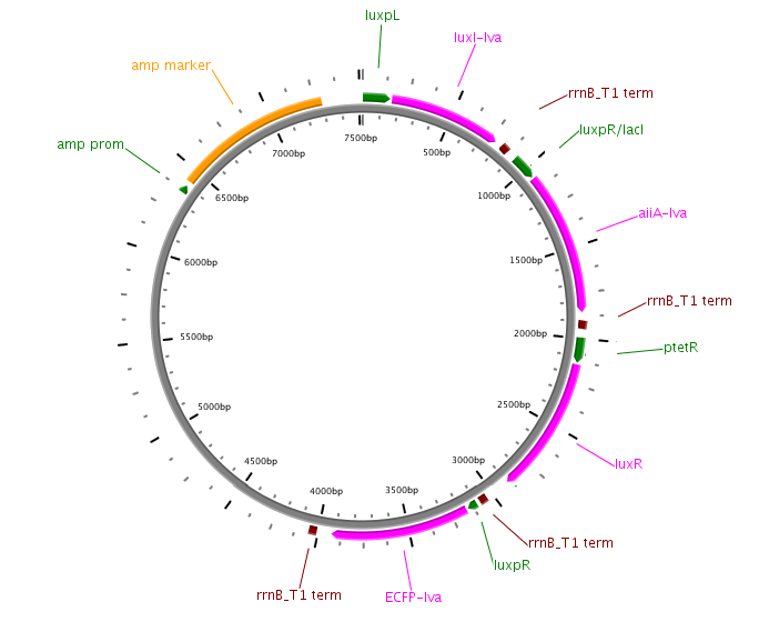
The first modification involves simply replacing the three copies of pLeft-LuxR with a single copy of LuxR behind a constitutive promoter (ptetR, Figure 5). This will significantly reduce the size of the construct (and the complexity of the system) while exhibiting similar behaviour. In addition to this modification, the pRight promoter regulating the expression of LuxI will be replaced by a pRight/lacI hybrid promoter. This should allow the oscillation circuit to remain inactivated until it is induced by adding a pulse of IPTG to the medium. The gene LuxR is under the control of the constituve ptet promoter and should give a steady transcription of the LuXR gene.
Fig.5. Circuit view of the streamlined design with ptetR regulating LuxR, and pRight/LacI (not indicated in circuit) controlling LuxI.
Fig.6. Streamlined design with ptetR regulating LuxR, and pRight/LacI controlling LuxI. All of the parts shown in the plasmid schematically have been located and verified in the Parts Registry.
Differential Feedback
The second major modification is the replacement of the inducible promoter pRight controlling expression of LuxI with the repressible pLeft. This will turn the LuxI-AHL positive feedback loop into a negative feedback loop, thus changing the dynamics of the system. Induction will be controlled using the pRight/lacI promoter regulating the AiiA gene. This is an experimental design, and will have to be validated with modelling work.
Fig.7. Genetic circuit of the experimental differential feedback loop.
Fig.8. Plasmid diagram of the experimental differential feedback loop.
Advanced application: luciferin regeneration
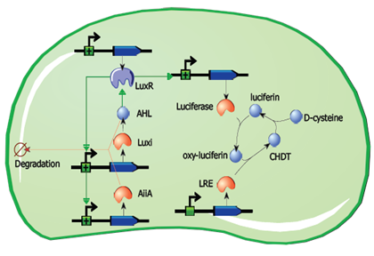
If the project advances and the reference design can be constructed and verified without significant delays, it may be possible to implement an advanced application involving luciferin regeneration. This design would involve the replacement of GFP with the Luciferase gene, and the addition of constitutively expressed Luciferin Regenerating Enzyme (LRE), which can regenerate the substrate required for the light-emitting reaction. Though the kinetics need to be considered, this design could theoretically produce regular pulses of visible light as long as cells are provided with sufficient D-cysteine.
Fig.9. A circuit for partially self-contained luciferin regeneration coupled to periodic luciferase expression.
Assembly
Plasmids
The plasmids will be constructed in accordance with the BioBrick assembly standard, which is a molecular cloning method with certain constraints. It requires that certain restriction sites be located upstream and downstream of the plasmid insert, but not anywhere else in the sequence. This enables modular assembly of low-level parts into larger composite parts, and the subsequent assembly of the large parts into even larger constructs without the need for special precautions. The exact strategy including each cloning step and the order in which parts are to be constructed is not shown here. The file contains all of the parts and included hyperlinks to the parts registry. Redundant strategies have been conceived of in order to prevent bottlenecks from arising due to certain parts being faulty. The optimal strategy allows all of the plasmids to be assembled completely by ligation of BioBrick parts. “Emergency” BioBrick part replacement strategies involving PCR have also been developed, and the necessary primers have been designed.
Strains
For all the cloning steps required in this project we will use high copy plasmids in order to make restriction and purification of the plasmids more efficient. The final constructs will be cloned into a low copy plasmid in order to avoid producing too much of the proteins, which could lead to noise related issues and the risk of inclusion body formation.
Experimental Design
Once the plasmids have been constructed and transformed into their final host system, the oscillation experiment can be performed. Cells should grow in a container with flowing medium until they reach an adequate cell density, and to then activate the oscillation circuit. Over the course of hours, levels of fluorescent light emission should rise and fall in a synchronized manner.
Fluorescence vs. Visible Light
Detection of the oscillatory behaviour in the previously described designs relies on the excitation of fluorescent proteins and detection their emissions. Replacing the GFP gene with a gene for Luciferase would allow visible-spectrum light to be emitted via a biochemical reaction if the appropriate substrate were added to the medium. Though they fulfil essentially the same function, which one is more suitable depends on the detection devices available and their compatibility with the platform on which the bacteria are grown. However, having visible light detection is a prerequisite for the implementation our advanced design.
Platform
The original Danino & Hasty design is believed to work in part due to the fact that the AiiA gene is longer than LuxI, and therefore the LuxI protein will begin producing the quorum sensing molecule AHL before AiiA is fully expressed. However, once AiiA is present it can degrade AHL faster than it is produced. Achieving oscillatory behaviour via this mechanism does not allow the system many degrees of freedom, and the kinetics involved, both in terms of gene expression and enzyme activity, are crucial. A self-contained system should not have to rely on external manipulation to produce oscillating behaviour. One aspect that can be controlled without compromising the integrity of the system is the rate at which AHL accumulates in the extracellular medium, and by extension, in all of the cells. This control can be provided by growing the cells in container in which they are physically constrained to a small space while a growth medium can flow over them and wash away AHL so that it cannot permanently accumulate, as well as waste and excess cells. It should also allow cell density to reach a stable steady state. The container should also be transparent to allow detection of the reporter molecules.
Microfluidic devices
The platform best suited for these requirements is a microfluidic device, such as the one used by Danino & Hasty. However, such devices need to be custom designed and are prohibitively expensive. Because the design contains cell traps (ca. 100x50x2μm) the devices are difficult to clean, and it is likely that each device could be used only once. The underlying virtue of using a micro fluidic device is that it is a container that allows high enough cell densities for achieving threshold AHL levels while allowing cell density to remain constant independent of medium flow rate. However, there exist a few alternatives that might fulfil the necessary requirements to serve as a platform for detecting oscillations. Some other alternatives besides the one already suggested, could be a standard microfluidic device (as opposed to a custom one) as offered by microliquid, these have a price around 150 euro’s a piece. This device consists of a linear channel which has an inflow and an outflow port. Danino & Hasty employed a similar design in his research of the propagation of the GFP signal. However, the dimensions of standard device are larger than the custom platform the micro-traps. Probably, this means that diffusion of the AHL will increase dramatically, slowing down oscillation periods. On the other hand, this device does not physically trap the cells the same way as the custom device. In this device the cells are trapped between the walls of the device locking them in place. These micro fluidic devices could be reusable.
Small Chemostat
A second alternative might be a small chemo-stat. One of the benefits of using a chemo-stat is that it is continuously stirred, and thus AHL levels are the same throughout the culture. Therefore the system is not dependent on AHL diffusion. Due to the nature of a chemo-stat there is a continuous out-flow of cells, which might be problematic for reaching sufficient cell densities, and which can produce high enough levels of AHL. One way of solving this could be to use a system in which cells are retained in the system via the means of membranes. Another alternative might be at the molecular level, wildtype LuxR is activated when AHL concentrations reach ~100 nM. In the registry of standard biological parts a mutant LuxR(BBa_I729004) is available, which is activated at a concentration of 10nM. Thus this mutant LuxR can in theory reduce cell densities 10 fold, but still allow a functioning system.
Microsieve
However, the most viable alternative to the microfluidic device might be a micro-sieve, these devices also trap cells just like a micro fluidic device. However the mechanism of entrapment is different, a micro fluidic device traps cells in a physical trap. Micro sieves do this by applying an overpressure. Through this overpressure cells are retained on the sieve. By varying the overpressure the “cake” of cells can be varied of thickness. Furthermore these sieves are chemically inert and can withstand harsh chemical and physical circumstances. Meaning that they can be cleaned and reused again. The device consists of a micro-sieve contained in a flow chamber. The micro-sieve is made of silicon and contains pores as small as 200 nm. Because the sieve is made out of silicon it is chemically inert and can easily be cleaned and reused. The flow chamber has an inflow and two outflow ports. Through the inflow port a liquid enters containing suspended particles. When the liquid passes the micro sieve it will encounters negative pressure whereby particles are trapped by the sieve. As particles accumulated, they eventually form a “cake”. The filtered liquid leaves the device via the outflow port below the sieve, and remaining liquid in the chamber leaves the device via the outflow port 1.
Fig.10. Schematic of a micro filtration device. The micro-sieve is 5x5mm.
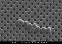
Fig.11. Photograph of cells growing on a micro-sieve.
This device is particularly promising for a few reasons. Through the negative pressure a small pore size filter is able to be seeded with micro-organisms that will grow on its surface, as depicted in Figure 11. Once these micro-organisms are trapped and growth medium is supplied as inflow, they will start to divide and form a tight layer on the sieve.
Furthermore by adjusting the flow rate or filter pore size and porosity the cell layer can be varied of thickness. This could be necessary for reaching the correct balance between AHL production and removal. Another reason why this device is promising is because of its low price. The company Aqua Marijn, which is partly located at the departed of organic chemistry can produce custom versions of the chamber and supply the micro filter for around 50 euros per device. Preliminary discussions with representatives have proven to be promising.
 "
"


