Design
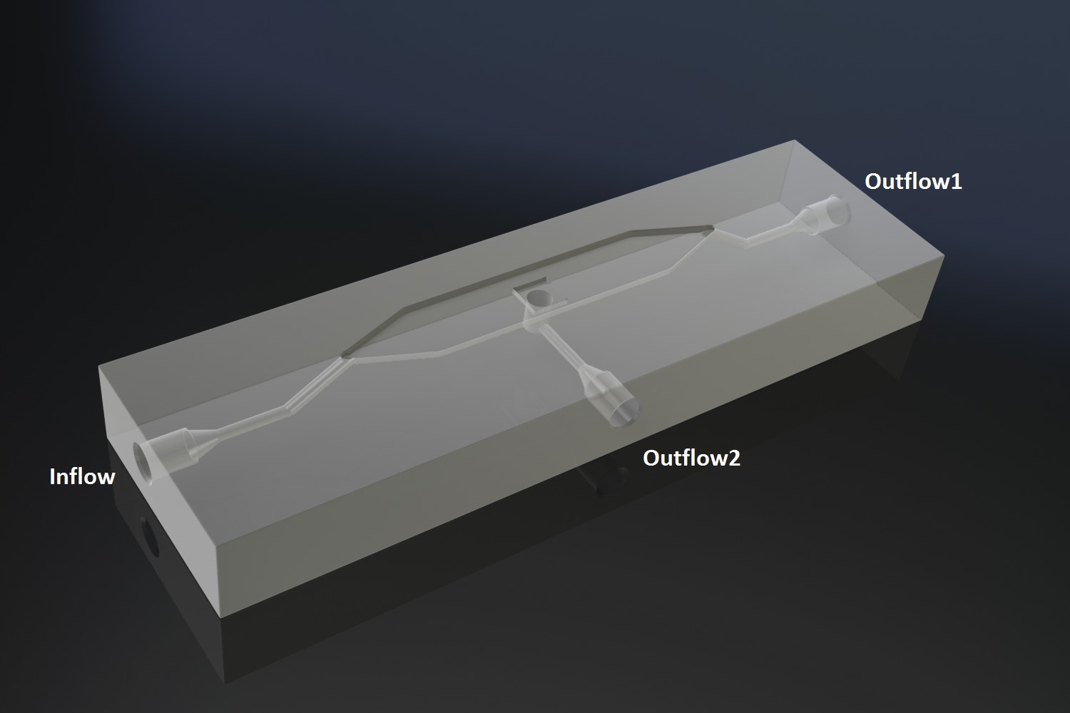
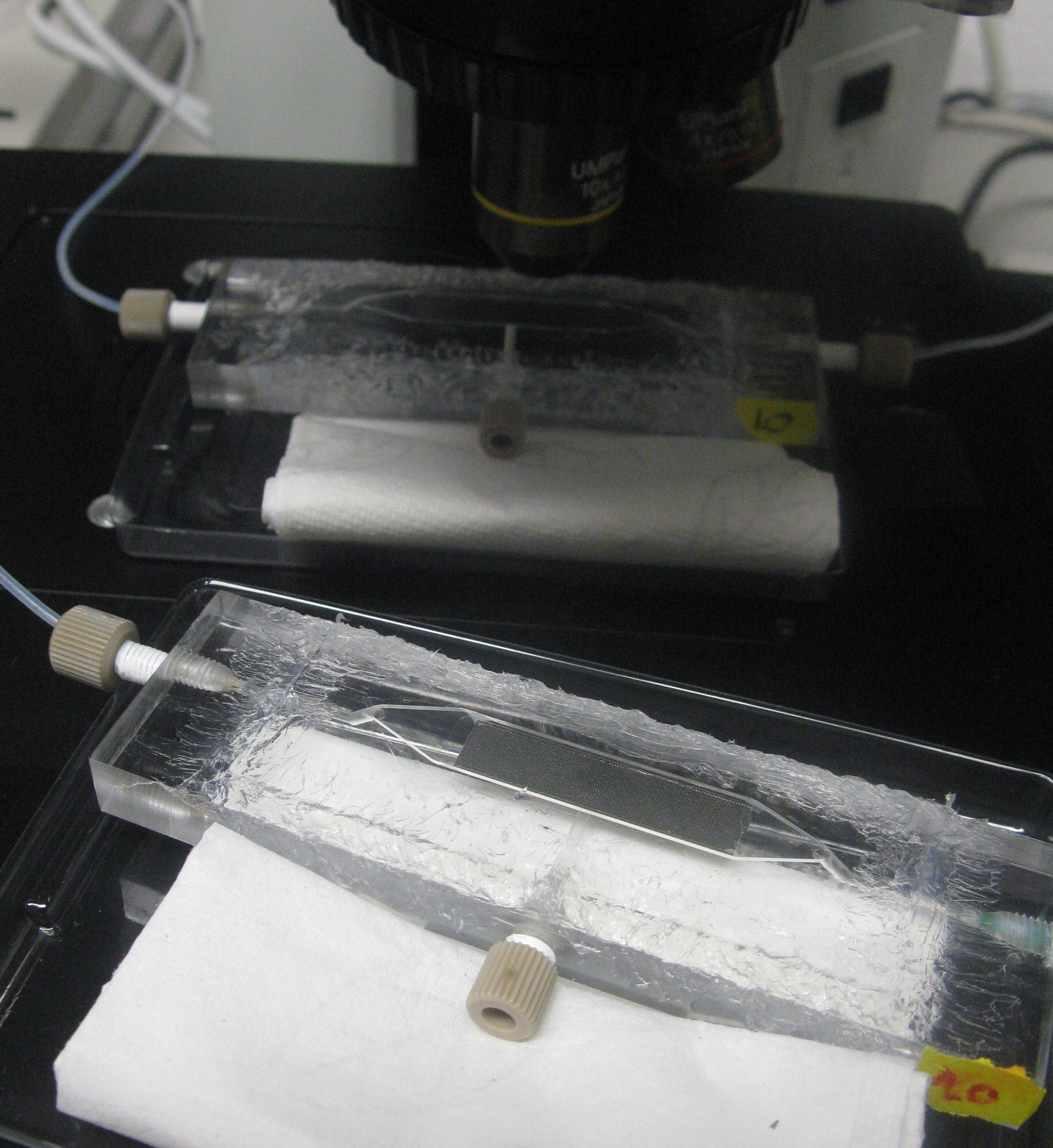
The [http://www.nature.com/nature/journal/v463/n7279/abs/nature08753.html paper] our system is based on used microfluidic devices to measure oscillations. Such microfluidic devices however are very expensive and our iGEM team budget was limited, so we decided to design a customary fluidic device, which was produced in the Wageningen University workshop. To keep as many options as possible open, the design implemented the idea of potentially accommodating two bacteria growing platforms, a micro-sieve and a micro-dish. Gaining more in-depth understanding of our system, we decided to focus on the micro-dish as platform to test the oscillatory behaviour of our construct. Figure 1 and 2 below show the flow chamber as original scetch designed by our team and the 3D rendered depiction of the final device.
Fig.1: Design of the fluidic device: original scetch and 3D render
The micro-dish contains porous wells, in which the cells can be physically constrained. It is placed in the socket of the dish, which allows a fluid to be flown over the wells. This fluid can be used to supply the cells with nutrients and wash away excess AHL and cells if necessary. Figure 2 shows a schematic of the device. The inflow and outflow1 can be used to flush the device with fresh medium. The use of outflow2 depends on the bacteria growing platform. In the case of the micro-sieve it can be used to create an under pressure, e.g. with a syringe, to trap the bacteria on the sieve. When using a micro-dish, it can optionally be used to bottom-feed the bacteria in the wells and/or supply additional substances to initalize the oscillatory behaviour of the system, e.g. IPTG in the case of the pRight/lacI hybrid promoter for the streamligned oscillator.
Fig.2: Schematic of the micro-fluidic device depicting the position of in- and outflow
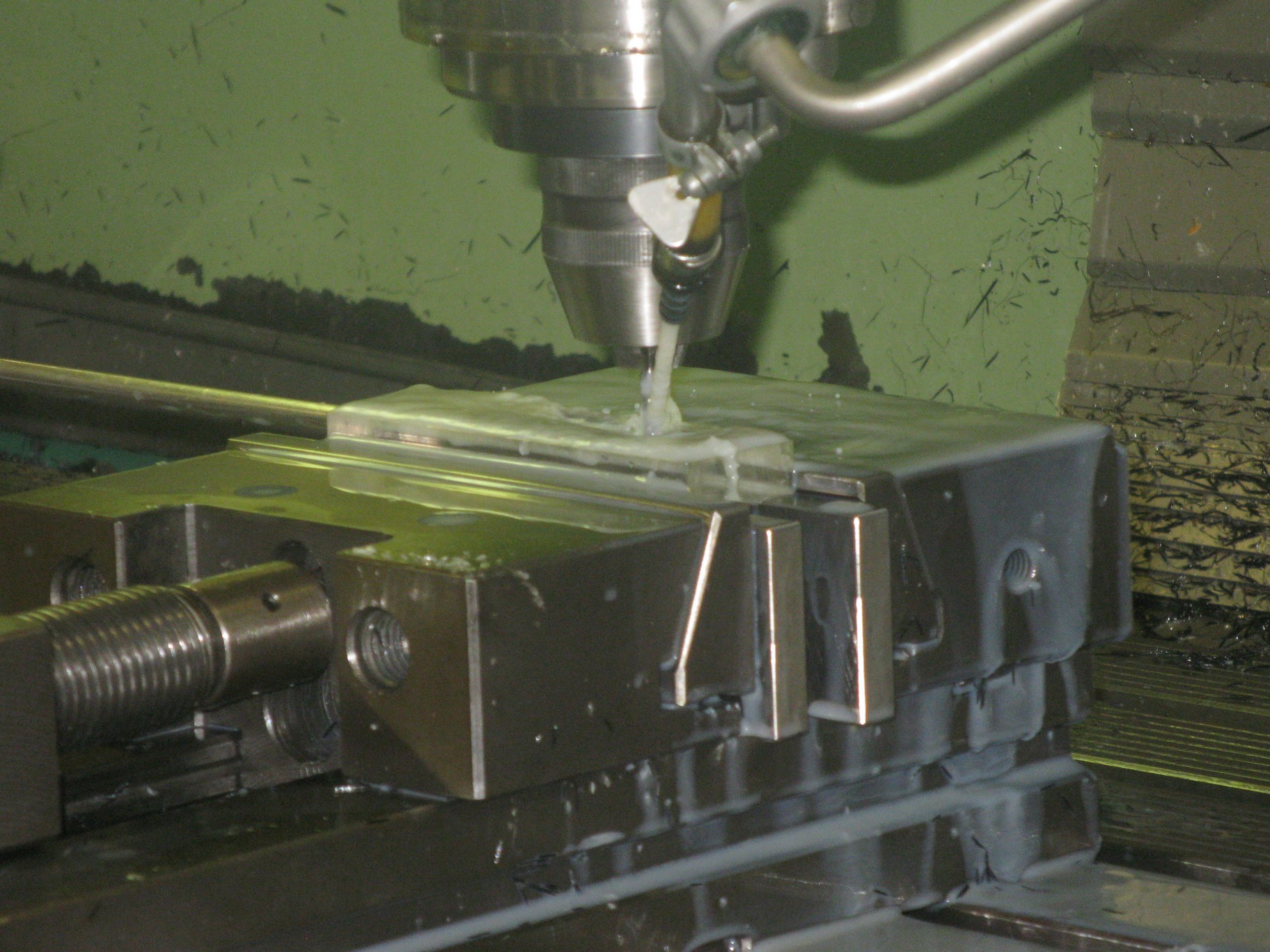 Fig.3: Production of the device in the Wageningen University workshop
Setup
The main concern for the setup of the device was to be able to gain control over the flow rate. According to Bernoulli's principle, the velocity of a fluid can be influenced by varying the height of the medium bottle. This approach was also used in the paper cited above. Figure X. shows the corresponding setup and the applying equations.
Fig.X: Setup of the device using Bernoulli's principle to control the velocity of the fluid.
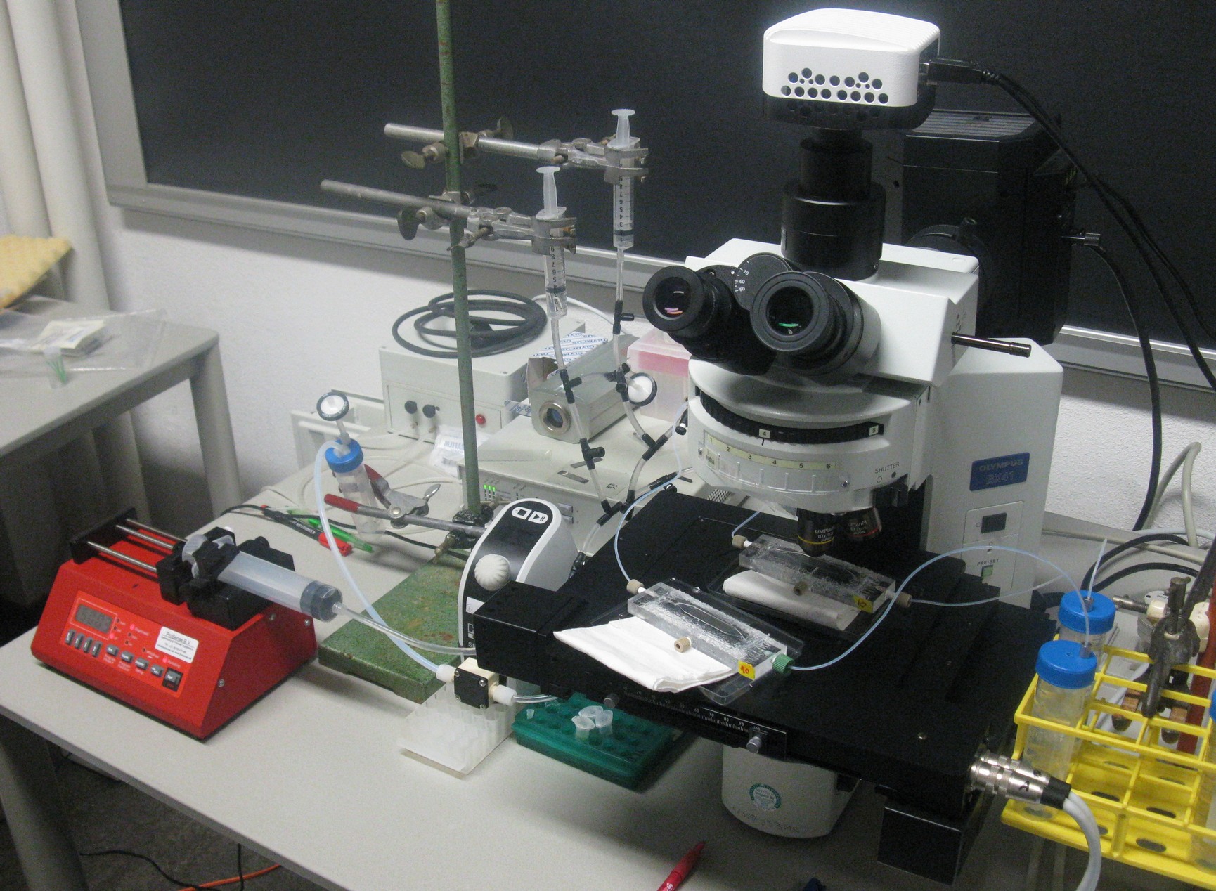
However, as mentioned on the modeling page, the dimensions of our fluidic device did not allow the aimed for precise control over the flow rate. This was tested both by calculating some theoretical values applicable for our device and running pilot experiments with water. Furthermore the obtained flow rates were also much faster than the flow rates in which oscillations were to be expected. This was solved by expanding our setup to incorporate the use of a syringe pump which controls the inflow. Figure X+1 shows the new setup.
Fig.X+1: Setup of the device using a pump to control the velocity of the fluid.
Measuring oscillations
.
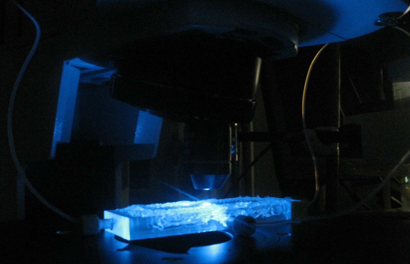
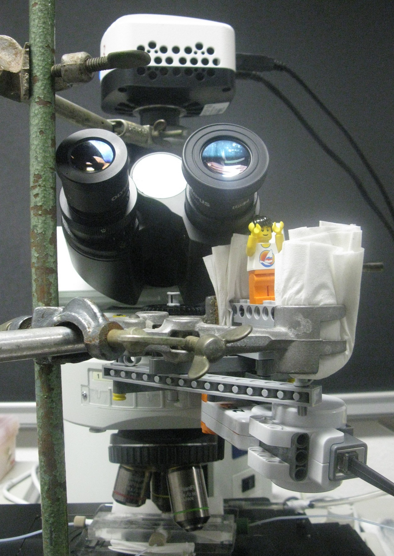
In order to be able to measure oscillations, the device was designed in such a way that it was possible to place it under a microscope.
Some fun facts about the device
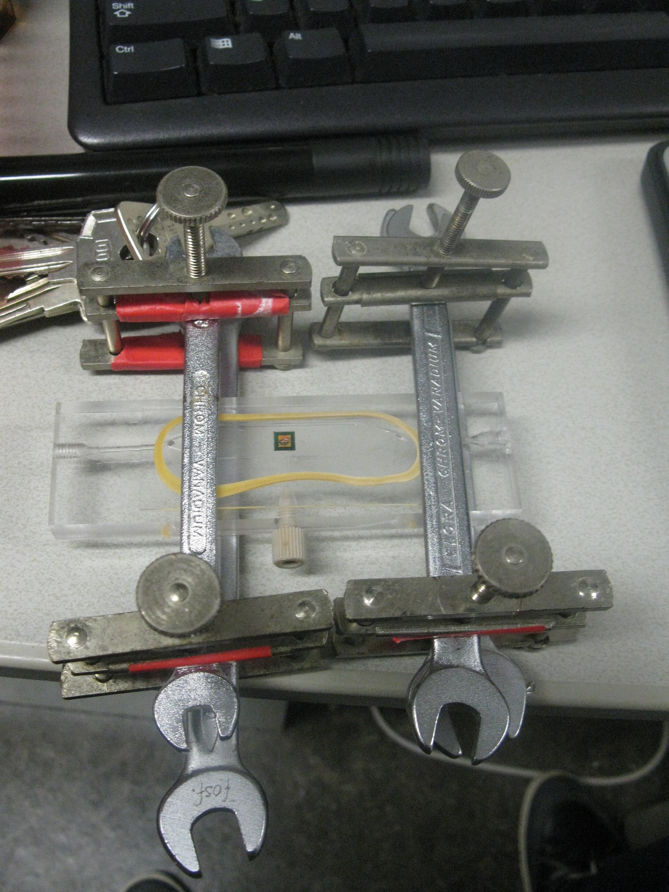
- Getting the chambre watertight was a lot trickier than expected and many creative ideas came up:
- In the end silicone glue used for sealing aquariums solved the problem.
- The tubing and valves used for the final setup of the device were bought at a local pet store.
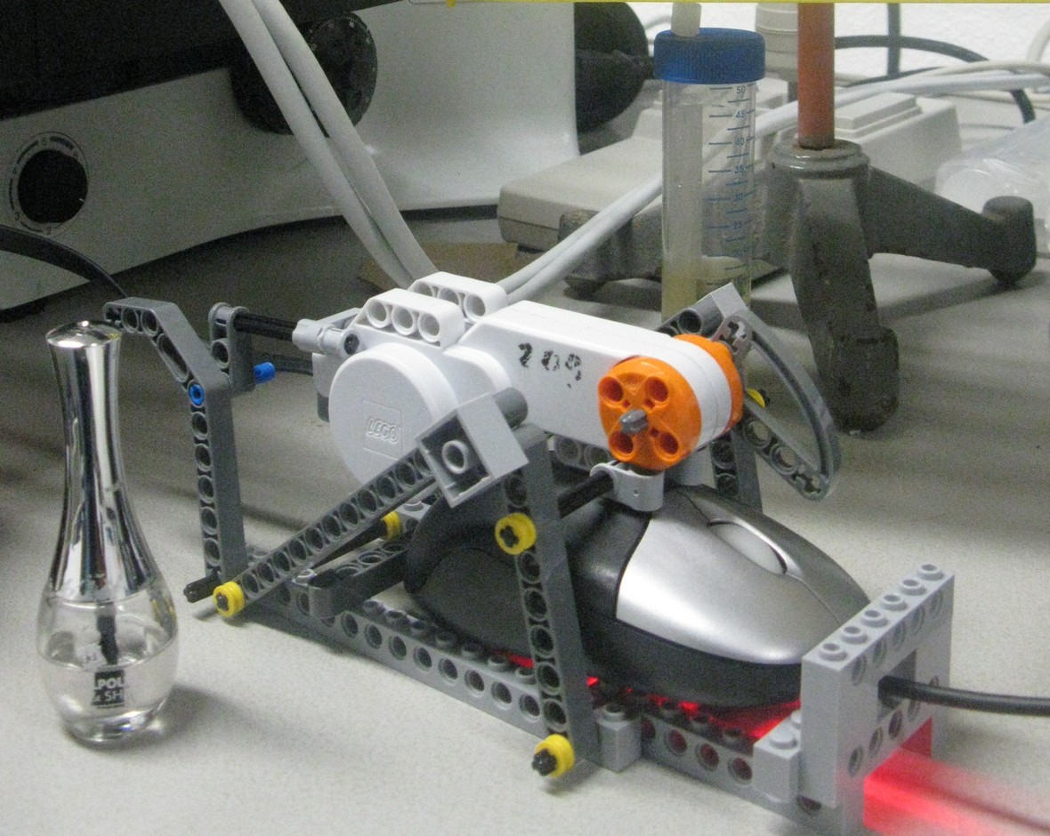
- During the first measurements, someone had to run to the microscope every ten minutes to take a picture. However, our team built a LEGO robot controlling the microscope which could take the measurements and give our team lots of time to work on other interesting things.
 "
"


