Design
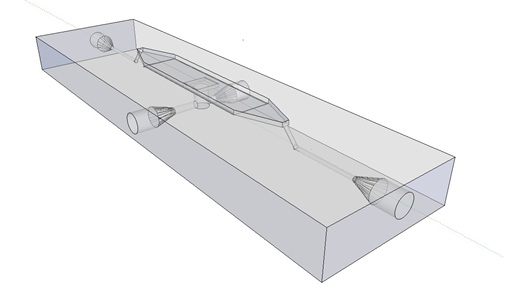
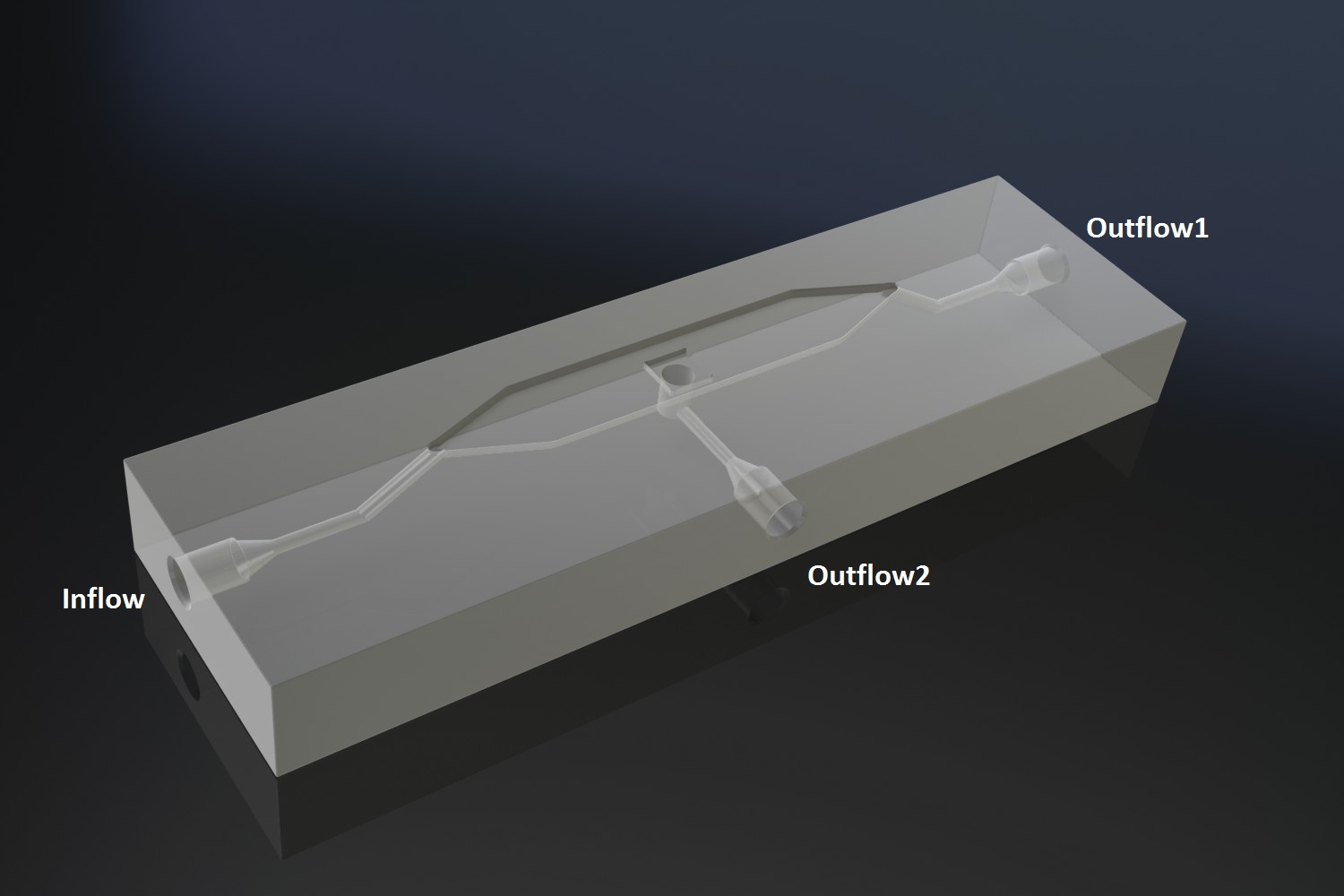
The [http://www.nature.com/nature/journal/v463/n7279/abs/nature08753.html paper] oscillatory system is based on, used microfluidic devices to physically constrain the host cells. This was necessary to induce and monitor oscillatory behaviour of a population of e.coli cells. Such microfluidic devices are very expensive and only usable for one experiment. Due to this we set out to find a cheap alternative for these microfluidic devices. Eventually we designed our own flow device, of which the design is seen in figure 1.
Fig.1: Wire frame model of designed flow device.
Bacterial growing platforms
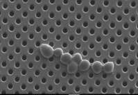
This flow device can accommodate two bacterial growing platforms, a micro-sieve and a micro-dish. The micro-sieve as depicted is figure 2 are membranes which have evenly distributed pores of 200 nm in diameter. These membranes are used in dairy industry to sterilise dairy products by removing micro-organism through filtration. Through filtration a cake of cells will form on the membrane, potentially giving us a platform capable of inducing and giving a mean of monitoring oscillatory behaviour of a population of e. coli cells.
Fig.2: Raster electron microscopy image of the micro-sieve with saccharomyces cerevisiae cells.
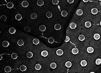
Another bacterial platform the micro-dish as depicted in figure 3 is a thin acrylic layer with pores which is superimposed on a layer of porous aluminium oxide. The wells seen in figure 3 have a diameter of 180 um and a depth of 40 um. Because the bottom of the wells are porous, nutrients can freely diffuse through the material to any cells contained in the well, these cells will divide until they are physically constraint by the borders of the well. Potentially giving us another platform capable of inducing and monitoring oscillatory behaviour of a population of e.coli cells.
Fig.3: Light microscopy image of the micro dish.
Implementation of both bacterial platforms in the design of the flow device.
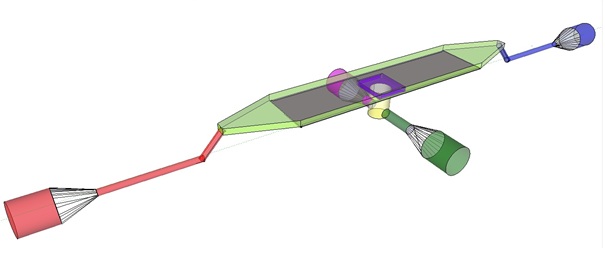
Potentially inducing and observing oscillatory behaviour in a population of e.coli cells with the means of using a micro-sieve, a cake of cells should be formed on the membrane. In dairy industry they do this by applying the filtrate through an inflow port leading to a chamber, which houses the micro-sieve. Because an overpressure is produced in the chamber liquid will be forced through the sieve, and the suspended particles in our case e.coli cells will aggregate on the sieve. However to prevent that the pressure in the chamber reaches a too high pressure that cells get lysed by being pushed through the filter also an outflow port is included. In the figure below the functional components of the flow device are depicted.
Fig.4: Functional components flow device: In red the inflow port and channel to the top chamber of the flow device. In light green the flow chamber containing either in black the micro-dish or in purple the micro-sieve. In blue the outflow port of the top chamber. In yellow the bottom chamber with it respective in and out flow channels and ports.
In our flow device outfitted with the micro sieve the inflow is depicted in red, the chamber in light green, outflow in blue and the through flow ports in green or pink.
For potentially inducing and observing oscillatory behaviour in a population of e.coli cells with the means of using a micro-dish. Nutrients should be readily available for the cells located in the wells. To achieve this the design implements a second set of inflow (in green) and outflow(in pink) ports, these ports connect to a chamber when filled with medium comes in contact with the aluminium oxide micro-dish(in black). Through the addition of these ports an continuous supply of fresh medium is supplied.
General design considerations.
Because we want to use the flow device in combination with fluorescence microscopy the distance between the objective and the sample is crucial. Due to this fact we choose for a top chamber depth of 1 mm because in combination with the deckled of 1 mm, this distance is still short enough for the focusing depth of the 20 x objective. Furthermore this also reduces the volume of the chamber, reducing overhead liquid which could contain precious reactants ,such as, acyl-homo-lactone. Another general design consideration was that we wanted to have an even flow over the microsieve. That,s why the in and out flow side of the top chamber are triangular because this will reduce flow differences over the sieve.
Fig.1: Design flow device made in google sketchup
The micro-dish contains porous wells, in which the cells can be physically constrained. It is placed in the socket of the dish, which allows a fluid to be flown over the wells. This fluid can be used to supply the cells with nutrients and wash away excess AHL and cells if necessary. Figure 2 shows a schematic of the device. The inflow and outflow1 can be used to flush the device with fresh medium. The use of outflow2 depends on the bacteria growing platform. In the case of the micro-sieve it can be used to create an under pressure, e.g. with a syringe, to trap the bacteria on the sieve. When using a micro-dish, it can optionally be used to bottom-feed the bacteria in the wells and/or supply additional substances to initalize the oscillatory behaviour of the system, e.g. IPTG in the case of the pRight/lacI hybrid promoter for the streamligned oscillator.
Fig.2: Schematic of the micro-fluidic device depicting the position of in- and outflow
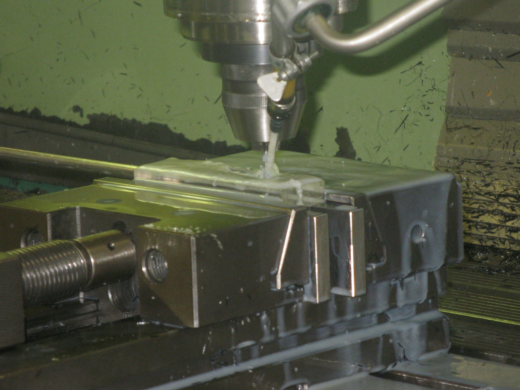 Left: Production of the device in the Wageningen University workshop
 "
"


