Team:Wageningen UR/Project/CompleteProject1Description
From 2011.igem.org
(→Synchroscillator) |
(→Synchroscillator) |
||
| Line 46: | Line 46: | ||
'''Fig.2.''' ''Genetic circuit of a synchronized oscillator'' | '''Fig.2.''' ''Genetic circuit of a synchronized oscillator'' | ||
| + | |||
'''Basic Components:''' | '''Basic Components:''' | ||
| Line 64: | Line 65: | ||
====3. Designs==== | ====3. Designs==== | ||
'''“Hasty” system:''' | '''“Hasty” system:''' | ||
| + | |||
[[File:Mainproject02.png]] | [[File:Mainproject02.png]] | ||
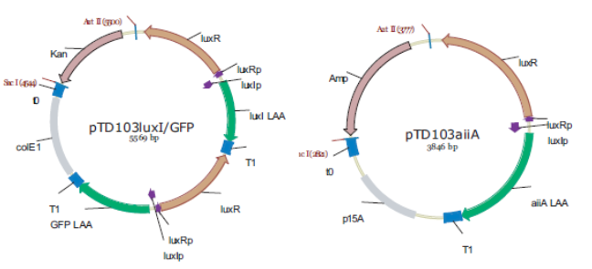
'''Fig.3.''' ''Synchronized Oscillator plasmids using natural quorum sensing system (Danino et al. 2010)'' | '''Fig.3.''' ''Synchronized Oscillator plasmids using natural quorum sensing system (Danino et al. 2010)'' | ||
| + | |||
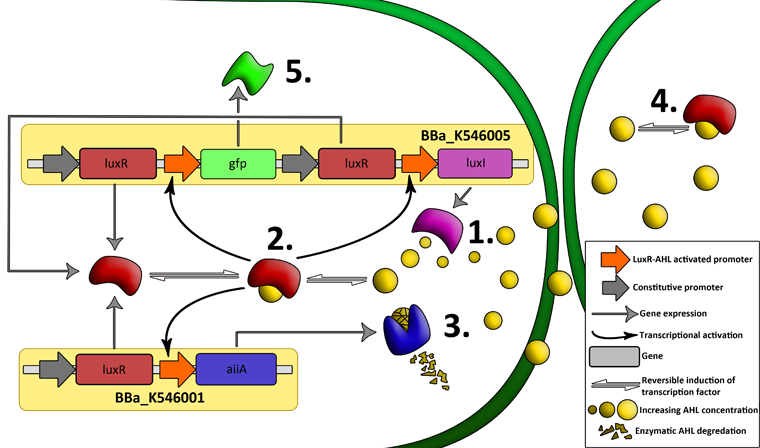
The first design we implemented was a BioBrick part based on reconstruction of the plasmids used by Danino et al. We intended to make as accurate a replica as possible in order to confirm the previously published results, and to test the viability of our experimental [https://2011.igem.org/Team:Wageningen_UR/Project/Devices platform]. However, there are a few differences between the original Hasty system and “our replica“. While the Hasty system employs the natural lux promoter which contains divergent pLeft and pRight elements (Fig 4), the BioBrick parts we employed have both elements in the same orientation. Both the original and our system contain 3 copies of the luxR gene under control of the pLeft element. Furthermore, a different (high copy) backbone was used during the functional validation of the parts, as opposed to the low copy backbone employed by Hasty. | The first design we implemented was a BioBrick part based on reconstruction of the plasmids used by Danino et al. We intended to make as accurate a replica as possible in order to confirm the previously published results, and to test the viability of our experimental [https://2011.igem.org/Team:Wageningen_UR/Project/Devices platform]. However, there are a few differences between the original Hasty system and “our replica“. While the Hasty system employs the natural lux promoter which contains divergent pLeft and pRight elements (Fig 4), the BioBrick parts we employed have both elements in the same orientation. Both the original and our system contain 3 copies of the luxR gene under control of the pLeft element. Furthermore, a different (high copy) backbone was used during the functional validation of the parts, as opposed to the low copy backbone employed by Hasty. | ||
| + | |||
[[File:Hasty1.png|x67px|link=http://partsregistry.org/Part:BBa_K546005]] | [[File:Hasty1.png|x67px|link=http://partsregistry.org/Part:BBa_K546005]] | ||
| + | |||
'''Fig.4.''' ''BioBrick part K546005 forms the positive feedback loop component of the basic synchonized oscillator. | '''Fig.4.''' ''BioBrick part K546005 forms the positive feedback loop component of the basic synchonized oscillator. | ||
| + | |||
[[File:Hasty2.png|x67px|link=http://partsregistry.org/Part:BBa_K546001]] | [[File:Hasty2.png|x67px|link=http://partsregistry.org/Part:BBa_K546001]] | ||
| Line 87: | Line 93: | ||
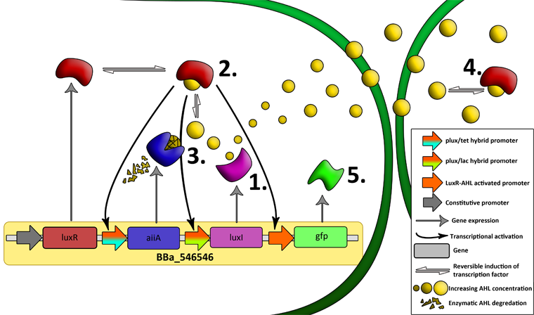
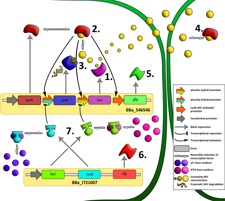
The aforementioned constraints are due to the fact that there are no means by which the expression kinetics of LuxI and AiiA can be externally influenced. In order to gain more control over the expression dynamics, we refactored the system and introduced “tuning knobs” in the form of chemically inducible hybrid promoters (pR/LacI inducible by IPTG and pR/tetR inducible by anhydrotetracycline). The addition of two independent control variables substantially expands the parameter space (cell density, flow rate) within which oscillations can occur. We also made the design more streamlined by taking advantage of the great diversity of available BioBrick quorum sensing parts in order to remove redundant elements and fit the entire system onto a single plasmid (a 30% reduction in size compared to the original design). Note: in order to take advantage of the tuning capabilities it is necessary to co-transform a plasmid which constitutively expresses LacI or TetR, or both. | The aforementioned constraints are due to the fact that there are no means by which the expression kinetics of LuxI and AiiA can be externally influenced. In order to gain more control over the expression dynamics, we refactored the system and introduced “tuning knobs” in the form of chemically inducible hybrid promoters (pR/LacI inducible by IPTG and pR/tetR inducible by anhydrotetracycline). The addition of two independent control variables substantially expands the parameter space (cell density, flow rate) within which oscillations can occur. We also made the design more streamlined by taking advantage of the great diversity of available BioBrick quorum sensing parts in order to remove redundant elements and fit the entire system onto a single plasmid (a 30% reduction in size compared to the original design). Note: in order to take advantage of the tuning capabilities it is necessary to co-transform a plasmid which constitutively expresses LacI or TetR, or both. | ||
| + | |||
[[File:System2.png|760px|link=https://static.igem.org/mediawiki/2011/a/a8/System2.png]] | [[File:System2.png|760px|link=https://static.igem.org/mediawiki/2011/a/a8/System2.png]] | ||
'''Fig.6.''' ''Genetic circuit of a synchronized oscillator'' | '''Fig.6.''' ''Genetic circuit of a synchronized oscillator'' | ||
| - | |||
| Line 97: | Line 103: | ||
'''Fig.7.''' ''Genetic circuit of a tunable synchronized oscillator'' | '''Fig.7.''' ''Genetic circuit of a tunable synchronized oscillator'' | ||
| + | |||
[[File:Dt.png|x67px|link=http://partsregistry.org/Part:BBa_K546546]] | [[File:Dt.png|x67px|link=http://partsregistry.org/Part:BBa_K546546]] | ||
| + | |||
'''Fig.8.''' ''The complete synchronized oscillator circuit with a single copy of constitutively expressed LuxR'' | '''Fig.8.''' ''The complete synchronized oscillator circuit with a single copy of constitutively expressed LuxR'' | ||
| Line 123: | Line 131: | ||
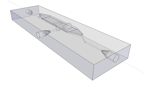
[[File:Mainpic.jpg]] | [[File:Mainpic.jpg]] | ||
| - | '''Fig.9.''' ''3D rendering of the flow chamber. | + | '''Fig.9.''' ''3D rendering of the flow chamber.'' |
| + | |||
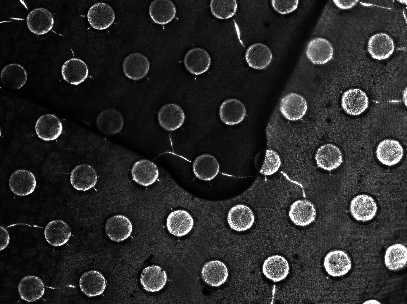
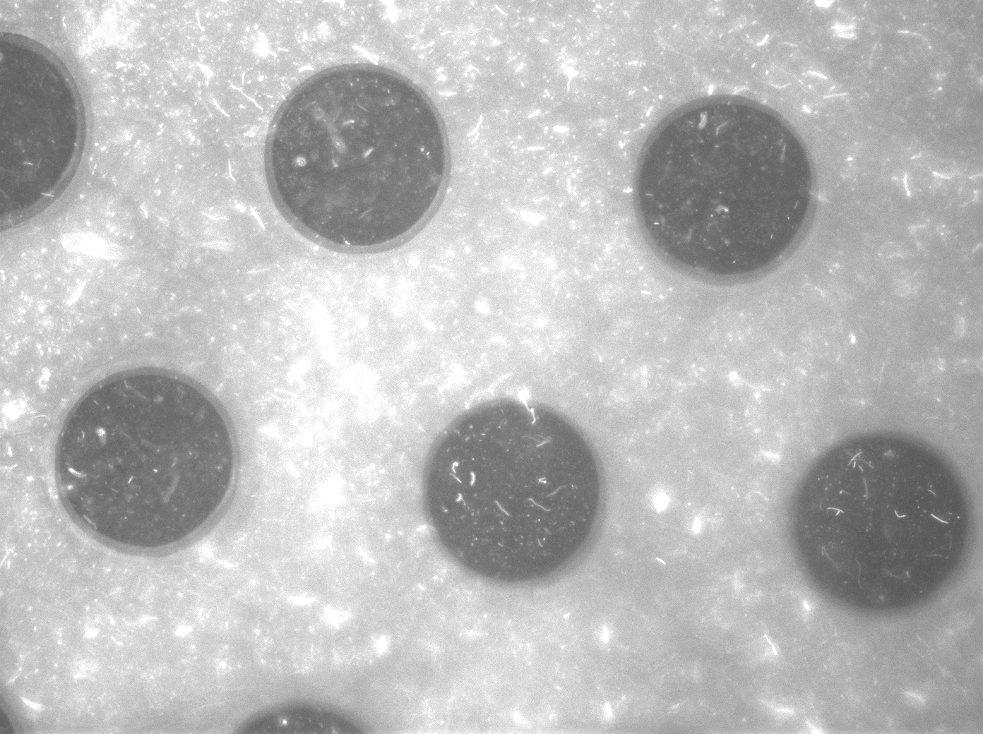
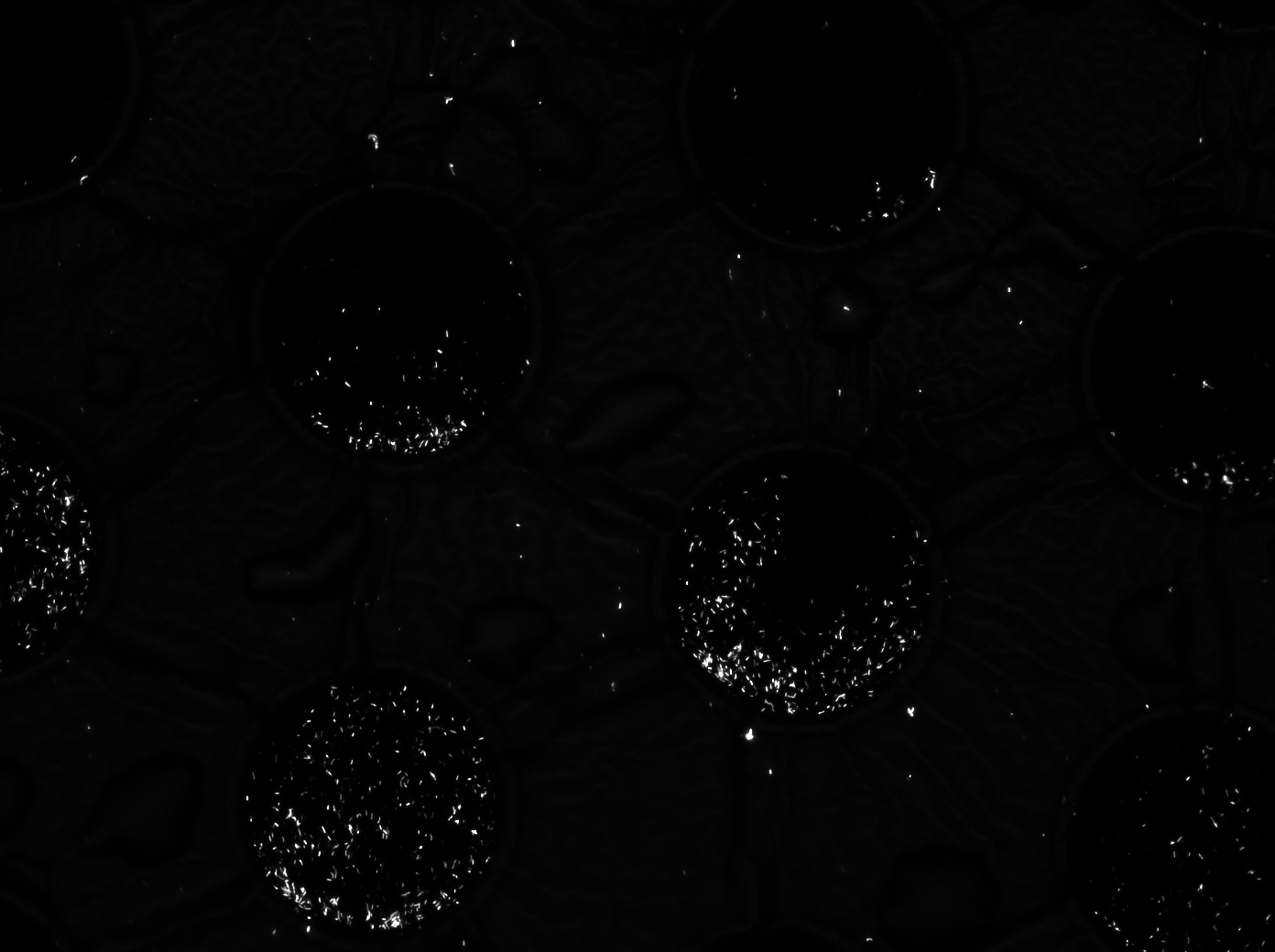
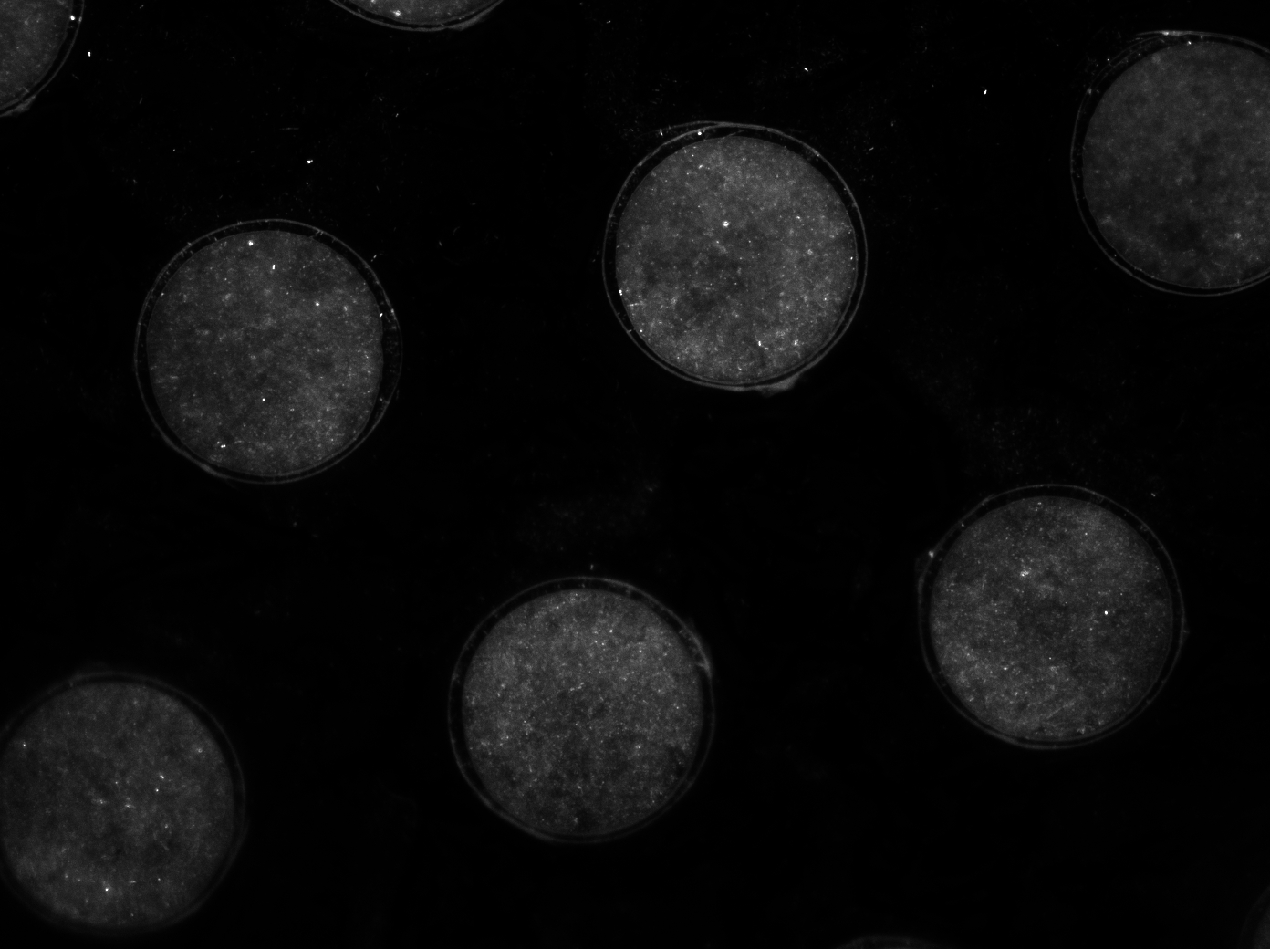
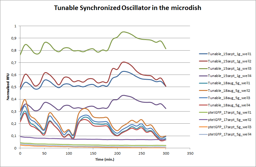
To measure the oscillations, the flow chamber was outfitted with a micro-dish, which is a thin aluminium oxide sheet containing thousands of circular wells. The wells are 180 μm in diameter and 40 μm deep. Small molecules (such as nutrients from growth media) can diffuse through the bottom of the dish and feed cells growing in the wells. For these experiments, the cells were fed through bottom in order to restrict their growth to the wells. This allowed the cells to reach high densities and relative stable populations which could be studied individually (5 wells could be visualized using 100x magnification) | To measure the oscillations, the flow chamber was outfitted with a micro-dish, which is a thin aluminium oxide sheet containing thousands of circular wells. The wells are 180 μm in diameter and 40 μm deep. Small molecules (such as nutrients from growth media) can diffuse through the bottom of the dish and feed cells growing in the wells. For these experiments, the cells were fed through bottom in order to restrict their growth to the wells. This allowed the cells to reach high densities and relative stable populations which could be studied individually (5 wells could be visualized using 100x magnification) | ||
| + | |||
[[File:Dish.gif]] [[File:Microdish_close.PNG|400px|link=https://static.igem.org/mediawiki/2011/3/3e/Microdish_close.PNG|right]] | [[File:Dish.gif]] [[File:Microdish_close.PNG|400px|link=https://static.igem.org/mediawiki/2011/3/3e/Microdish_close.PNG|right]] | ||
'''Fig.10.''' ''Above: Schematic illustration of the micro-dish.'' | '''Fig.10.''' ''Above: Schematic illustration of the micro-dish.'' | ||
| - | |||
| Line 136: | Line 145: | ||
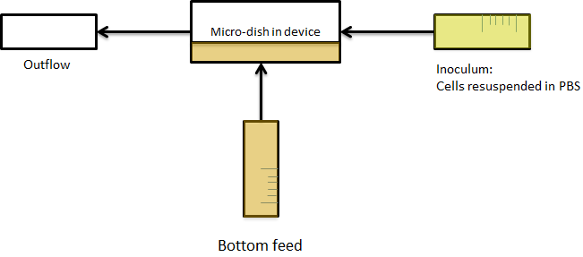
| - | The cells containing the synchronized oscillator system plasmid were grown overnight in LB medium supplemented with an antibiotic. They were then centrifuged for 10 minutes at 4600 rcf and resuspended in Phosphate Buffered Saline solution before being injected through the top flow port (Fig. | + | The cells containing the synchronized oscillator system plasmid were grown overnight in LB medium supplemented with an antibiotic. They were then centrifuged for 10 minutes at 4600 rcf and resuspended in Phosphate Buffered Saline solution before being injected through the top flow port (Fig.12a). Directly after injection, the cells fill the entire chamber volume (Fig.13a). After approximately 5-8 hours the cells situated outside the wells are starved and no longer express detectable levels of GFP (Fig.13b). Cells in the wells continue to grow for approximately 12 hours before reaching a stable cell density (Fig.13c). After the wells were saturated with cells, time lapse microscopy was initiated. A photograph was taken every 10 minutes using a fluorescence microscope fitted with a GFP filter. Changes in GFP expression over timewere subsequently quantified. (Video 1) |
| - | + | ||
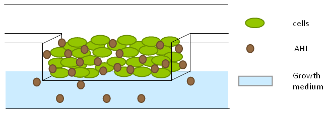
[[File:Bottom_feed_WUR.png|380px]] [[File:Zero-flow.PNG|380px]] | [[File:Bottom_feed_WUR.png|380px]] [[File:Zero-flow.PNG|380px]] | ||
| + | |||
| + | '''Fig.12a.''' ''Schematic view of the bottom fed flow device.'' '''Fig.12b.''' ''three dimensional impression of cells in the flow device'' | ||
| + | |||
[[File:Fullchamber.PNG|250px]] [[File:Dish_cells.JPG|250px]] [[File:4pbs_experiment_incubatenewof17.8_DT_5g_dry.jpg|250px]] | [[File:Fullchamber.PNG|250px]] [[File:Dish_cells.JPG|250px]] [[File:4pbs_experiment_incubatenewof17.8_DT_5g_dry.jpg|250px]] | ||
| + | |||
| + | '''Fig.13a.''' ''Cells in the chamber, directly after injection.'' '''Fig.13b.''' ''Cells in the chamber, a few hours after injection.'' '''Fig.13c.''' ''Cells in the chamber, about twelve hours after injection'' | ||
Revision as of 00:10, 22 September 2011
 "
"


