Team:Peking S/project/blogic
From 2011.igem.org
Template:Https://2011.igem.org/Team:Peking S/bannerhidden Template:Https://2011.igem.org/Team:Peking S/back2
Template:Https://2011.igem.org/Team:Peking S/bannerhidden

Boolean Logic
Boolean Logic Synthetic Microbial Consortia|
Extension of the Boolean Logic
Boolean Logic Synthetic Microbial Consortia
We have harvested, re-designed and quantitatively characterized enough ‘chemical wires’ for developing this ‘chemical wire’ toolbox. But this was not the end. We noticed that there is actually a trade-off between signaling speed and layers of cell-cell signal transduction when distributing a logic function among a synthetic microbial consortium. More layers there are, more time needs to be cost during signal transduction, but with less difficulty implementing each layer.
To figure out how to cope with this trade-off, we next sought to propose design rules and thus to develop software to facilitate the distribution of Boolean logic gene network among a synthetic microbial consortium.
Design Rules and Software for Boolean Network Distribution
We have assigned a set of these three logic gates, AND, OR and NOT as our logic bases (Figure 1-3), not only because they are regarded as elementary parts in electronics, but also taking into account that there have been well established modular AND and OR gate [1, 2], and our quorum sensing repressors serve naturally as NOT gate. Moreover, this set is functionally complete, which is to say that any computational operation can be implemented by layering these gates together (Figure 4).
Besides, this set is also modulated. This is to say, any computational operation can be implemented by layering these gates together, and that this set can be rapidly connected to different inputs and used to drive different outputs (Andersen, [1]).
Figure 1. Schematic view of AND gate. T7ptag is a T7 RNA polymerase gene with two internal amber stop codons blocking translation, while supD is the amber suppressor tRNA. Only when both components are transcribed, T7 RNA polymerase is synthesized and this in turn activates a T7 promoter. Afterwards, T7 promoter would turn on the downstream gene expression as an output. The input promoters and output gene expressions can be changed according to the practical use of our AND gate, which guarantees its modularity.
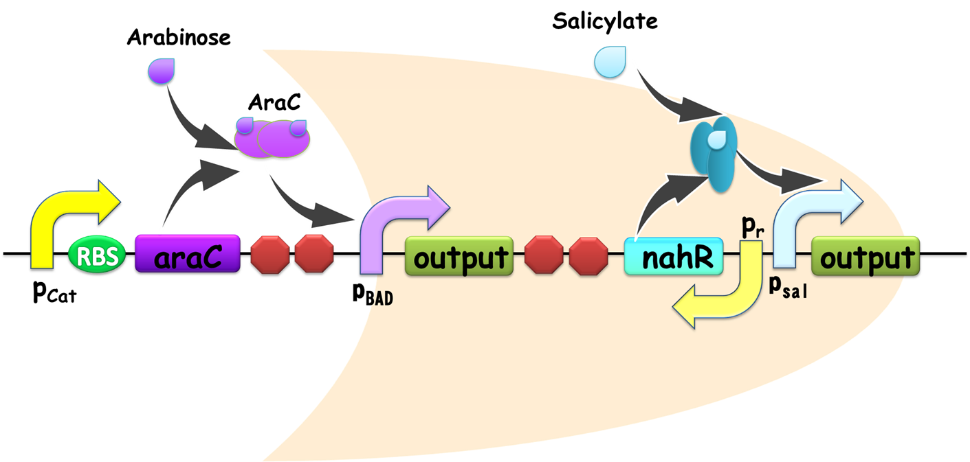
Figure 2. Schematic view of OR gate. Two promoters, pBAD and pSal share a same output gene, so if any one of them is on, the output gene would be generated, and the gate is ON. Similar with our AND gate, the input promoters can be readily substituted in practical use, establishing its advantage for modular use.
Figure 3
Modeling for AND, OR and NOT gates have been established.
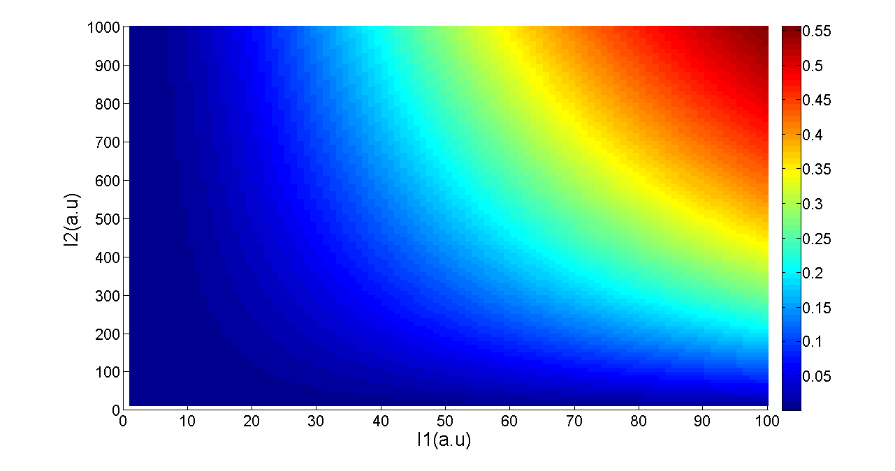
Transfer functions of AND gate[1] is:
Where Gmax is the maximum fluorescence observed for the output, I1 and I2 should be the activity of the input promoter (a=50+/-20, b=3000+/-1000).;
Figure 5. Transfer function of AND gate. I1 and I2 denote two inputs of the AND gate. Only when two inputs both present in the system, the output would be ON.
When two promoters controls the transcription of a gene, the promoters can either be additive or interfere with each other. In most case, tandem promoters are nearly additive. In our design of OR gate, the two promoters seldom interfere each other since they regulate separated identical output genes (Figure 2), and as a consequence it is reasonable only discuss additive situation.
The production of X is modeled as [1]:
When two promoters controls the transcription of a gene, the promoters can either be additive or interfere with each other. In most case, tandem promoters are nearly additive. In our design of OR gate, the two promoters seldom interfere each other since they regulate separated identical output genes (Figure 2), and as a consequence it is reasonable only discuss additive situation.
Equation 1 reduces to the following at steady-state:
(x is the concentration of inducer).
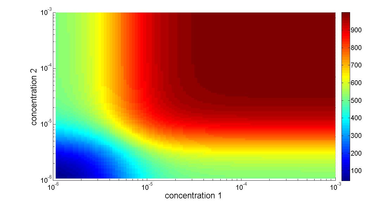
Basing on formula (2) to (4), we get the simulation result:
 Figure 6. Transfer function of OR gate. Concentration 1 and 2 denote two inputs of the OR gate. When any one of the two inputs presents in the system, the output would be ON.
For our NOT gate (quorum sensing repressors), the binding of a ligand to its transcription factor at equilibrium is:
where C is the concentration of bound transcription factor, C0 is the total concentration of transcription factors, L is the concentrations of ligands, Kd is the dissociation constant, and n is the cooperativity. By mass conservation, the concentration of free transcription factor CF is:
The probability for each promoter in open is described by the following equations:
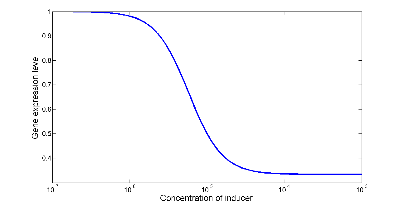
Basing on formula (5) to (7), we get the simulation result:
 Figure 7. Transfer function of NOT gate. When the inducer presents in high concentration, gene expression would be inhibited, while low concentration of inducer would activate gene expression, exhibiting a typical performance of NOT gate.
As a proof of principle, we have exhausted all possible Boolean logic functions with two inputs and one output. We speculated that the first design rule is to find out the simplest construction of each two-input logic gate, where 'simplest' was defined as the fewest logic bases utilized in the whole network.
In addition, if several layouts can be generated for a specific logic circuit using the same number of logic bases, we tended to select the one using more NOT and OR, since these two gates are easier to be assembled into cells and cause less metabolic burden compared with AND gate.
We have developed a specific Breadth-First-Search (BFS) method to find out each combinational logic circuit meeting the design requirements. First of all, the outputs A and B could be readily obtained without any logic bases. Then we applied NOT, OR and AND gate respectively to the established circuits, resulting in NOT A, NOT B, A OR B and A AND B. Once again, by connecting the newly-obtained logic gates using the three bases, we could construct more new gates, and similarly repeated procedures would generate all the sixteen combinational logic gates, and the BFS method itself would guarantee that all the combinations of logic bases we have found are the simplest ones corresponding to our definition. The CPP source files of our calculation as well as the program are available on our wiki. download
 "
"


