Team:Calgary/Project/Promoter/Final Data
From 2011.igem.org


Electrochemical lacZ Characterization

Introduction
In order to be able to utilize the electrochemical detection system, various response levels must be correlated to cell concentration. Because our output signal is the product of a reaction sequence, it would not be sufficient to only characterize the performance of one particular part operating alone. This novel approach to characterizing lacZ through the oxidation of chlorophenol red was done in conditions allowing all the necessary reactions to occur simultaneously - just as if used in a field-ready biosensor.
The conditions in which the detection can occur depend on two main features. The first important point that needed to be optimized was the buffer solution present. To optimize this we screened various candidates found from the papers that planted the idea of electrochemistry in our head. The second point that had to be optimized was the plating of the electrode. After speaking to various graduate students in labs that perform electrochemistry we tested the suggested metals and found our ideal plating technique. These optimization results can be found here.
Results
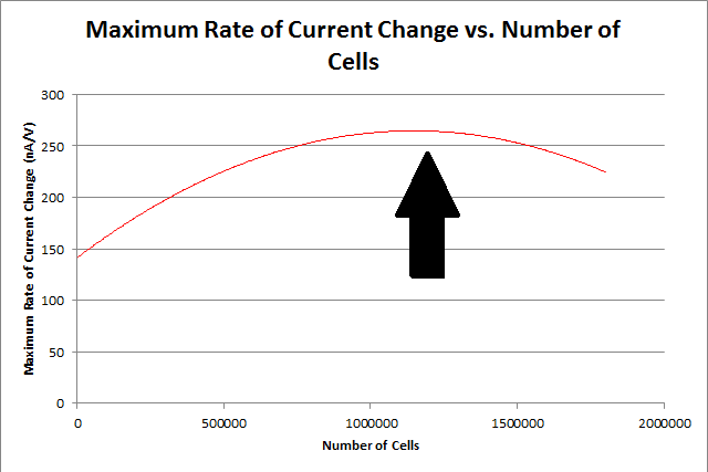
The final results of our data processing is shown in Figure 1 below. The calculations done to arrive at this final curve follow.
By repeating this procedure for the various tested cell levels, we can construct one of our standard curves - the maximum rate of current change versus number of cells.
We determined the concentration of cells in our culture to be 7.35*108 cells/mL. For the purposes of making a biosensor, we can see that having 105 to 107 cells in our electrochemical system provides a strong signal, while not risking saturating our detection mechanism. This is completely feasible with a small amount of our cell culture.
Appendix
In order to construct our standard curve for current response vs. number of cells, several experiments were conducted with varying numbers of cells, with a constant amount of CPRG (100uL at 0.5M), NaH2PO4 buffer (1mL at 0.5M), and nanopure water (up to 20mL). The cell was left for 5 minutes before the experiment was run.
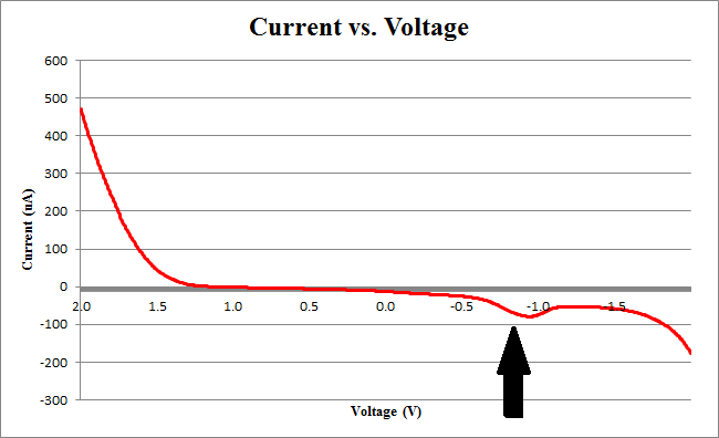
Figure 2 below shows experimental data for a cyclic voltammetry experiment done with 7.5*105 cells.
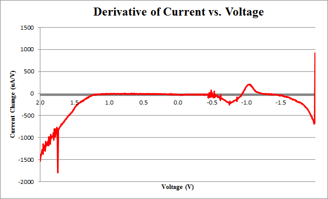
We observe the characteristic dip indicative of CPR oxidation at approximately -0.71V, showing the presence of CPR in solution. Next, the time derivative of this curve will be taken, shown below.
Using Figure 3, we determine the maximum rate of change of current to occur at -0.755V, with a maximum of 258.45uA/V.
By repeating this procedure for the various tested cell levels, we can construct one of our standard curves - the maximum rate of current change versus number of cells.
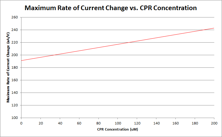
Finally, by varying the amount of CPR in solution, and running cyclic voltammetry experiments in a simple system of only CPR, buffer, and nanopure water, we can construct a standard curve of CPR concentration versus maximum rate of current change. This graph is shown below.
Currently, work is being done to refine our ability to differentiate between varying levels of CPR concentration.

 "
"


