Team:Potsdam Bioware/Project/Details
From 2011.igem.org
Details
Lorem ipsum dolor sit amet, consetetur sadipscing elitr, sed diam nonumy eirmod tempor invidunt ut labore et dolore magna aliquyam erat, sed diam voluptua. At vero eos et accusam et justo duo dolores et ea rebum. Stet clita kasd gubergren, no sea takimata sanctus est Lorem ipsum dolor sit amet. Lorem ipsum dolor sit amet, consetetur sadipscing elitr, sed diam nonumy eirmod tempor invidunt ut labore et dolore magna aliquyam erat, sed diam voluptua. At vero eos et accusam et justo duo dolores et ea rebum. Stet clita kasd gubergren, no sea takimata sanctus est Lorem ipsum dolor sit amet.
Microviridin
Lorem ipsum dolor sit amet, consetetur sadipscing elitr, sed diam nonumy eirmod tempor invidunt ut labore et dolore magna aliquyam erat, sed diam voluptua. At vero eos et accusam et justo duo dolores et ea rebum. Stet clita kasd gubergren, no sea takimata sanctus est Lorem ipsum dolor sit amet. Lorem ipsum dolor sit amet, consetetur sadipscing elitr, sed diam nonumy eirmod tempor invidunt ut labore et dolore magna aliquyam erat, sed diam voluptua. At vero eos et accusam et justo duo dolores et ea rebum. Stet clita kasd gubergren, no sea takimata sanctus est Lorem ipsum dolor sit amet.
Phage Display
Cloning
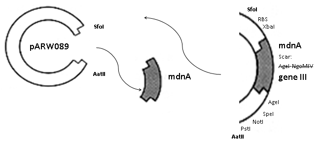
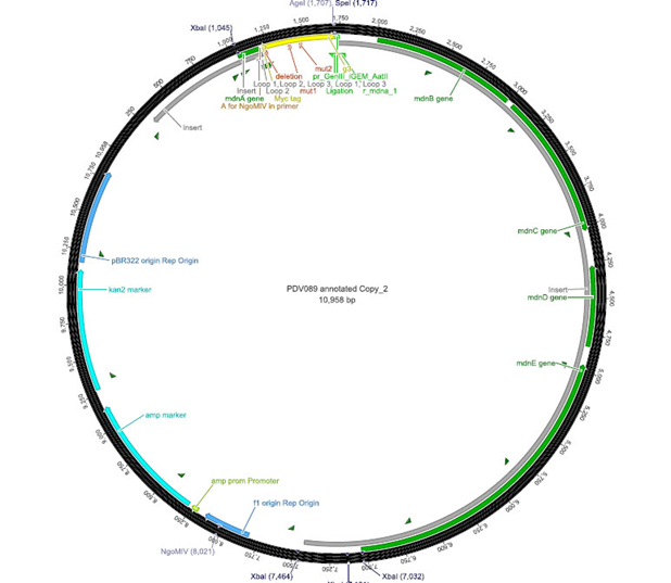
The phage display vector pPDV089 was derived from the plasmid pARW089 which carries the whole mdn-cluster. This plasmid contains a plasmid origin of replication and additionally a f1 ori which enables the packaging of single strand DNA into phages. For selective amplification ampcillin and kanamycin resistance genes are included. To create the phagemid pPDV089 standard cloning procedure were performed.
First mdnA was deleted by excising using the restriction enzymes SfoI and AatII. The next step comprised the introduction of a mdnA-gene III-fusion gene. Therefore gene III was amplified from pak100blaKDIR and mdnA from pARW089 by PCR. The primers were designed to enable the introduction of iGEM and other restriction sites required for further cloning steps. The purified PCR product gene III was digested by NgoMIV and AatII whereas the PCR product mdnA was digested by SfoI and AgeI. Subsequent the three fragment ligation of mdnA and gene III into the digested vector has been conducted. Thus a mdnA-gene III-fusion part according to RFC25 was generated whereby AgeI and NgoMIV overhangs are compatible and placed in frame with the protein sequence. The ligation of AgeI and NgoMIV overhangs resulted in a scar coding for the threonine and glycine. Because the introduction of restriction sites before mdnA leaded to a great distance between ribosome binding site and mdnA a second RBS was inserted among SfoI and XbaI recognition sites to ensure a sufficiently expression rate of the mdnA-gene III-fusion gene. The myc sequence located between mdnA and gene III allows the detection of the expression of the mdnA-gene III-fusion protein on the surface of the phage using western blot or ELISA. In the last step the kanamycin resistance gene was disturbed because for phage display the selection of cells carriyng both helper phages and the phagemid is beneficial and the helper phages have a kanamycin resistance too. Therefore a 300 bp fragment of the kanamycin resistance gene was deleted using the restriction enzyme NsiI which had two recognition sites in the kanamycin gene.
 | 
|
| cloning strategy of the BioBrick | phagemid pPDV089 | |
ELISA
The next step was the detection of the expression of the mdnA-myc-gene III-fusion gene on the surface of the phage. So E. coli cells strains XL1-Blue and ER2738 were first transformed with the phagemid pPDV089 before they were infected with helper phages. E. coli cells containing both plasmids were selected. An ELISA test was performed to determine whether these cells are able to produce phage particles carrying the mdnA peptide on their surface. To perform this test anti-c-myc-antibodies were immobilized on ELISA plates and incubated with purified phages. For detection a second antibody coupled with horse radish peroxidase (HRP) was used which binds the gene VIII protein of the phages. The HRP substrate 3,3'-5,5'-Tetramethylbenzidine (TMB) was added and in case of binding a colour reaction was expected. The colour shift from achromatic to yellow in wells incubated with phages produced in XL1-blue cells showed the successful expression of mdnA-gene III-fusion protein on the phages.In wells which should be incubated with ER2738 cells no colour change was obserevd what is due to the fact that a mistake during phage purification was noticed.
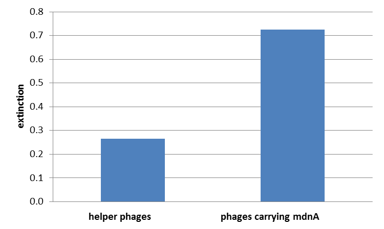
For more precise results the absorption from 450 – 600 nm was measured and measured data was presented in a box plot. As a negative control helper phages were added instead of produced phages, carrying mdnA-myc-gene III-fusion protein on their surface. Furthermore two wells were prepared were the secondary antibody was not added.
The graphic shows clearly the much higher absorption measured in wells, which were incubated with phage particles of interest produced in XL1-Blue cells. As has already pointed out this shows the succeeded expression of mdnA-c-myc-gene III-fusion protein on the surface of the phages.
Phage Display
To test the fundamental suitability of this screening method, phages representing unmodified mdnA on their surface and phages not representing mdnA in a ratio of one to one were incubated with immobilized trypsin which is known as a target of mdnA. The display was conducted in ELISA plates. The bound phages were eluted using a buffer with low pH value and neutralized afterwards. To check how many phages interacted with trypsin, E. coli cells were re-infected with eluted phages and plated on agar with different antibiotics. Cells infected with phages carrying mdnA are expected to grow on agar with ampicillin whereas cells containing phages without mdnA are expected to grow on agar with kanamycin. To control the success of the panning round additionally E. coli cells were infected with not panned phages and plated on agar. Subsequent the number of clones grew on ampicillin and kanamycin before and after panning was compared. During the running of this step it was noticed that much more cells infected with unpanned phages grew on kanamycin plates than on ampicillin plates. This is surprising and indicates that phages were not given in one to one ratio as calculated after nanodrop measuring but in a 1:400 ratio (phages carrying the protein of interest: helper phages). Thus the suggestion can be made that maybe the presented mdnA on the phages has some toxic effects on the cells.
The results of the first phage display performed after one panning round are plotted in the figure below ("Grown clones after Phage Display 1"). It was expected that after panning the ratio of cells grown on ampicillin and cells grown on kanamycin increases. This is attributable to the fact that cells which grow on ampicillin should contain the phage particles carrying mdnA c-myc geneIII fusion protein on their surface and are expected to bind specifically to trypsin. Unfortunately this could not be observed in this experiment.
So it was decided to repeat this experiment under improved conditions. Therefore the number of washing steps during the described experimental procedure was increased.
Results are shown in figure
So after that repeated and modified phage display a much higher ratio of cells grown on ampicillin before panning and cells grown on ampicillin after panning to cells grown kanamycin before panning and cells grown on ampicillin after panning could be noticed. This indicates that the unmodified mdnA expressed on the phages binds specifically to the immobilized trypsin and that phage display in general for screening a generated mdnA library is possible.
In Vivo Selection
Lorem ipsum dolor sit amet, consetetur sadipscing elitr, sed diam nonumy eirmod tempor invidunt ut labore et dolore magna aliquyam erat, sed diam voluptua. At vero eos et accusam et justo duo dolores et ea rebum. Stet clita kasd gubergren, no sea takimata sanctus est Lorem ipsum dolor sit amet. Lorem ipsum dolor sit amet, consetetur sadipscing elitr, sed diam nonumy eirmod tempor invidunt ut labore et dolore magna aliquyam erat, sed diam voluptua. At vero eos et accusam et justo duo dolores et ea rebum. Stet clita kasd gubergren, no sea takimata sanctus est Lorem ipsum dolor sit amet.
Modelling
Motivation
There is no synthetic biology without modeling, of course. In principle there is structure modeling and system modeling. In structure-modeling the conformation and structure of proteins is examined and steric consequences for reactions or the whole system can be estimated. We focused on the second sort of modeling: The systems modeling in which the reaction kinetics of the whole system is analysed and outcomes are predicted. Thus a synthetic biology approach can be chosen because a better understanding of the system is achieved and further changes can be planed - just like in engineering.
Model
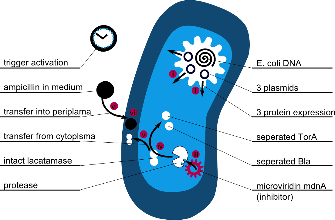
The following schema shows the major reactions taking place in our cell system. The Romanic numbers indicate the place of reactions that were written down as equations and then numerically propagated through time. We were able to see that our system works very well in theory. We learned about correct time-scales for our triggering and we were able to identify expected cell-division rates as reference for lab work.
The schema shows the triggered expression of mircoviridin (our inhibitor), the protease (that needs to be inhibited for medical reasons) and the lactamase (that is destroyed by the protease and works as an indicator for our system because it is a protection against ampicillin).
There are three important trigger activation times:
(t0) - beginn (microviridin added already)
t1 - start expression of protease
t2 - start expression of lactamase
t3 - ampicillin added into medium
(t4) - end of the experiment: cellcultures survive or die.
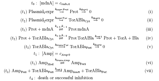
Keeping these times in mind, the reactions can be written down in seven chemical reaction equations of different sort and order.
Concentration equations
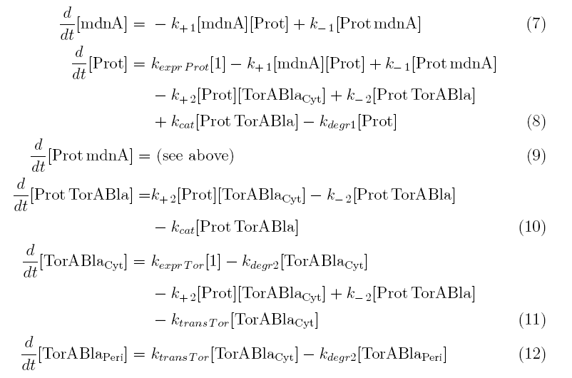
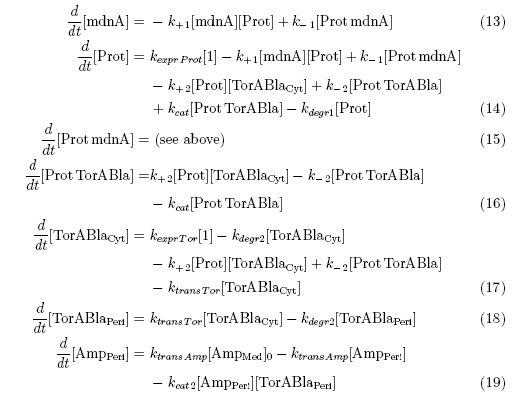
From the above reaction equations differential equations can be derived that describe the change of substance concentrations. Three concentrations are fixed, however:
All other concentrations can be represented in form of differential equations. Between time t1 and t2 four factors are introduced:
k+1 in (1/s*#molecules)- factor for association of mdna (microviridin) and Prot (protease)
k-1 in (1/s) - factor for dissociation of the inhibited protease
kexpr.prot in (#molecules/s) - factor for the expression of protease
kdeg1 in (1/s) -factor for degradation of protease
Between time t2 and t3 six additional factors are introduced:
k+2 in (1/s*#molecules)- factor for association of Prot (protease) and TorABla (lactamase)
k-2 in (1/s) - factor for dissociation of protease and substrate
kcat in (1/s) – factor for the catalytic enzyme reaction that cuts lactamase in inactive parts
kexpr.Tor in (#molecules/s) - factor for the expression of lactamase
kdeg2 in (1/s) – factor for degradation of lactamase
ktransTor (1/s) – factor by which lactamase in the cytoplasm is able to pass the membrane and get into the periplasm
After t3 there are only two more factors that we should introduce:
ktransAmp (1/s) – factor by which the added ampicillin in the medium is able to pass the outer membrane and get into the periplasm
kcat2 in (1/s*#molecules) – factor for the catalytic enzyme reaction that cuts lactamase in inactive parts
Results
The equations above were solved using MATLAB. Using the Avogadro constant and the volume of a E.coli cell (10^-15L) and a periplam-volume of about 5%, following konstants were calculated and compared with similar literature values:
k+1 = 1.e-6 (1/molecules*s)
k-1 = 2.e-4 (1/s)
kexpr.Prot = 1 (molecules/s)
kdegr1 = 3.e-3 (1/s)
k+2 = 5.e-7 (1/molecules*s)
k-2 = 4.e-4 (1/s)
kcat = 8 (1/s)
kexpr.Tor = 1.4 (1/s)
kdegr2 = 3.e-3 (1/s)
ktransTor = 3.e-3 (1/s)
ktransAmp = 3.e-3 (1/s)
Kcat2 = 0.3 (1/molecules*s)
MIC(0) = 8000 (molecules)
AMP(0) = 5000 (molecules)
It can be seen that there is only a negligible amount of ampicillin in the periplam if the expression works as indicated. There is also a wide tolerance left for suboptimal conditions. The triggertime t1, t2 and t3 shal be about one hour after one another.
In the first section the effect of the inhibition can clearly be seen: Even though the continuous expression of protease, only a very small number remains active in the cytoplasm. In the second section lactamase is expressed. Most of the lactamase in the cytoplasm is destroyed by the protease, however the number is by far large enough to steadily release molecules into the periplam where it cannot be affected by the protease any more. Because the volume of the periplasm is very small, the concentration there is even higher than the absolute amount of molecules in the graph suggests compared to the amount of molecules in the cytoplam. The third section shows that the concentrations remain very steady and the cells are ampicillin resistent.
Cells passing this procedure are very ampicillin resistent and grow fast: They double their cell volume about every 20 minutes. If an error would appear and the ampicillin concentration inside the periplasma would increase over 2µg/ml, the growth rate would slow down drastically and the cells might die. This way defect cell cultures can easyly be seperated from the good ones.
The ratio of ampicillin concentration in n µg/ml to the growth rate (cells double during this timespan) is approximatelly this: T(groth) = 20min+10*2^(n-1).
MATLAB code
Media:conzt1.m
Media:conzt2.m
Media:conzt3.m
Media:plottfuntionendreiaufeinmal2.m
 "
"
