Team:Calgary/Project/Reporter/Prototype
From 2011.igem.org


Prototype

What is a Potentiostat?
To implement the electrochemical reporter technique we needed a very specific hardware part. This part is called a potentiostat and is essentially a combination between a multimeter and a power source. It can supply and measure both current and voltage between its three electrodes. For our purposes it needed to do three tasks at once; supply a voltage between the counter and working electrodes, measure the resulting current, and measure the voltage between the counter and reference electrodes. The data from the first two tasks can be used to determine the conductivity of the solution. It can also be graphed in a current vs voltage graph. On this graph, the oxidation of CPR can be seen by a rapid change in current.
The last measurement, the voltage between the counter and reference electrodes, is used to increase the precision of the supplied voltage. Some reactions can change the observed potential at the counter or reference electrodes. This potential change causes errors in the measured data. Since the reference electrode is not undergoing any reactions, it can be used to determine and compensate for any potential change at the other electrodes.
The testing input is generated by a laptop and sent to the prototype using a digital to analog converter. The output goes back to the laptop through an analog to digital converter. The converters are needed for the laptop to properly process the data.
Building a Prototype
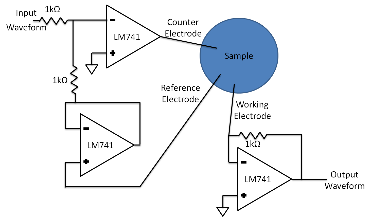
While we used a commercial potentiostat for our lab measurements, we also developed our own hardware. In principle a potentiostat is very simple and can be built using only six parts: three operational amplifiers (op amps) and three resistors. Op amps are electronic parts that produce a voltage many times greater than the difference between its input terminals. They are commonly used to amplify voltages. Two resistors and two op amps are used to set up the counter and reference electrodes, which form the data input section. The remaining resistor and op amp are used to convert the current coming into the working electrode into a voltage which is sent to the laptop via an analog to digital converter.
The easiest way to assemble a prototype is to use a breadboard because it makes it very easy to switch connections and parts. This is not only necessary if something is wired wrong or an op amp fails, but also when the gain needs to be adjusted. The gain is a value that indicates how many times greater the input is compared to the output. It needs to be adjusted if the output becomes either too large or too small to be properly processed.
Below is a circuit diagram of our potentiostat. This diagram can be used to build a prototype that has the same detection range as our potentiostat. The design is highly modifyable, and can have parts altered without destroying all functionality.
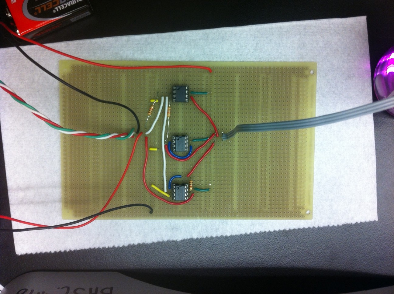
After we tested our prototype design with a breadboard circuit we decided to take the prototype one step further and create a soldered version. While it uses the same kind of parts it is smaller, which makes it easier to work with. The result is shown below.
Note that we used 9V batteries to supply power to the op amps. On the breadboard we had access to 15V which we used. The only difference is that the output signal doesn’t have as wide of a range now that we are using the 9V batteries. They also have the advantage that they are widely available.
Next Steps
The next step would be to miniaturize our circuit and create a printed circuit board. Printed circuit boards have the advantage of integrated wires, meaning the wires are small copper lines on the board instead of physical wires sticking up from the board.

 "
"


