Team:Calgary/Project/Reporter
From 2011.igem.org
| Line 11: | Line 11: | ||
<span id="practice"><h2>Why Electrochemical?</h2></span> | <span id="practice"><h2>Why Electrochemical?</h2></span> | ||
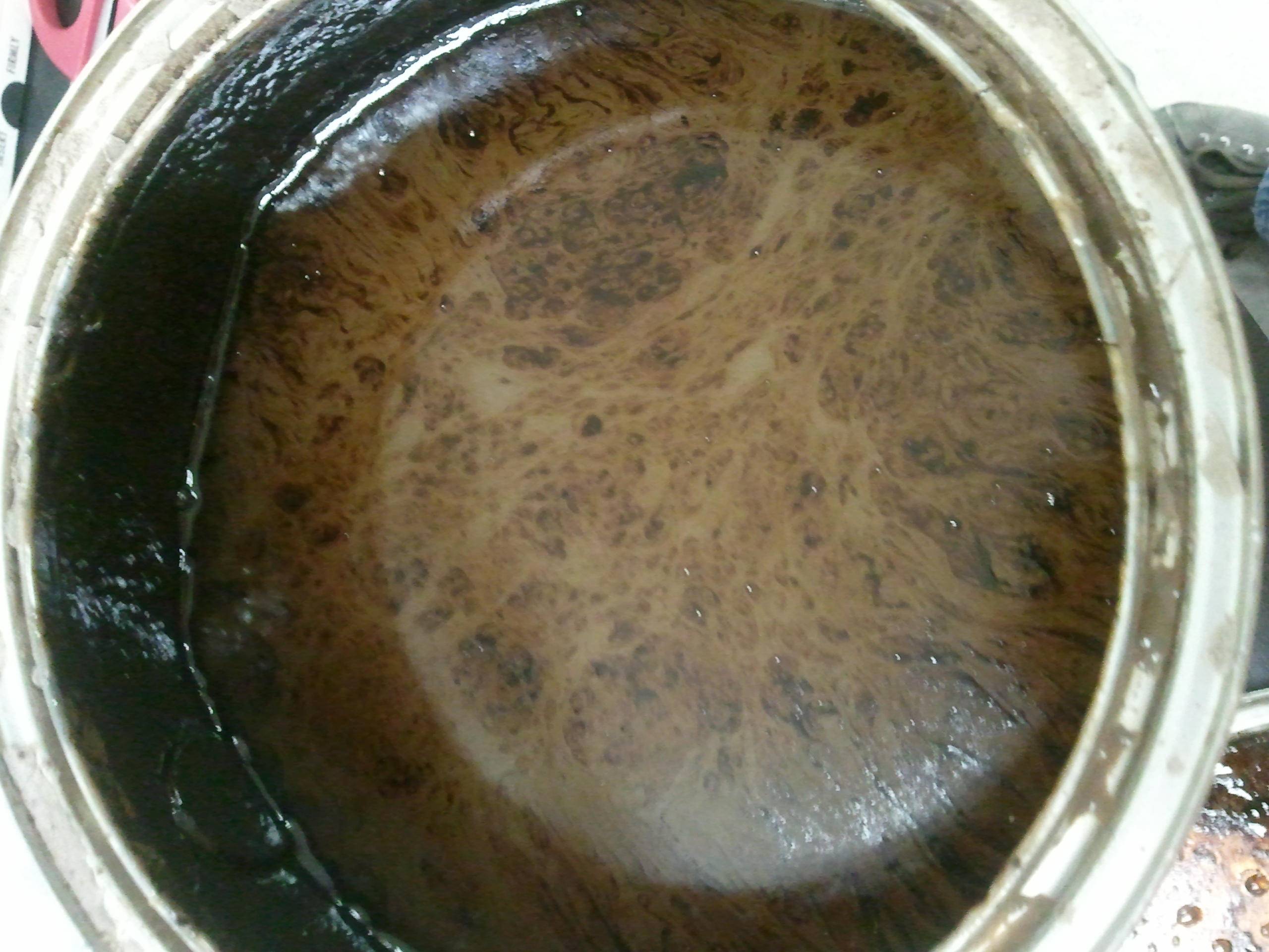
<p>Oilsands tailings ponds samples are difficult to work with for several different reasons. First of all, tailings ponds samples are murky, and can have greatly varying compositions from pond to pond. It would be difficult to obtain accurate colorimetric data from these samples, and it would be similarly difficult to readily observe fluorescence. Because an electrochemical response does not rely on being able to see anything, Team Calgary determined the electrochemical reporter to be ideal for this purpose.</p> | <p>Oilsands tailings ponds samples are difficult to work with for several different reasons. First of all, tailings ponds samples are murky, and can have greatly varying compositions from pond to pond. It would be difficult to obtain accurate colorimetric data from these samples, and it would be similarly difficult to readily observe fluorescence. Because an electrochemical response does not rely on being able to see anything, Team Calgary determined the electrochemical reporter to be ideal for this purpose.</p> | ||
| + | |||
| + | </html>[[image:UofC_tpw.jpg|thumb|200px|center|<b>Figure 1</b> Tailings pond water is often murky and turbid, with an unknown composition of pollutants within.]]<html> | ||
<p>Electrochemical reporters offer several advantages over visually-determined reporters. The signal is robust - environmental factors such as the presence of pollutants or sample turbidity do not affect the signal. Every molecule has a different oxidation potential - because we know the exact oxidation potential for our analyte, we can easily tell the difference between our desired signal and background noise. Another advantage of an electrochemical response is that the data is immediately available in digital form. This allows for fast graphical interpretation of the data as well as maximum information collection from the data. </p> | <p>Electrochemical reporters offer several advantages over visually-determined reporters. The signal is robust - environmental factors such as the presence of pollutants or sample turbidity do not affect the signal. Every molecule has a different oxidation potential - because we know the exact oxidation potential for our analyte, we can easily tell the difference between our desired signal and background noise. Another advantage of an electrochemical response is that the data is immediately available in digital form. This allows for fast graphical interpretation of the data as well as maximum information collection from the data. </p> | ||
| Line 25: | Line 27: | ||
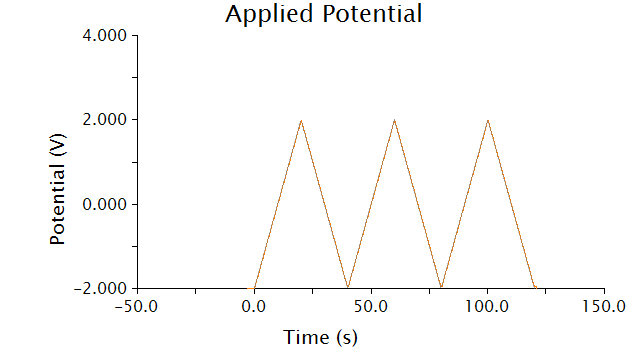
<p>The voltammetric technique we used to detect chlorophenol red was cyclic voltammetry - the input voltage is shown below.</p> | <p>The voltammetric technique we used to detect chlorophenol red was cyclic voltammetry - the input voltage is shown below.</p> | ||
| - | </html>[[image:Calgary2011_appliedpotential.png|thumb|400px|center|<b>Figure | + | </html>[[image:Calgary2011_appliedpotential.png|thumb|400px|center|<b>Figure 2</b> Applied potential across the cell during cyclic voltammetry.]]<html> |
<p>As voltage slowly increases and decreases, each species present in solution will undergo a redox reaction at its respective oxidation potential. Because we know the oxidation potential of our analyte, chlorophenol red, we can ignore any background noise or pollution using this method.</p> | <p>As voltage slowly increases and decreases, each species present in solution will undergo a redox reaction at its respective oxidation potential. Because we know the oxidation potential of our analyte, chlorophenol red, we can ignore any background noise or pollution using this method.</p> | ||
| Line 31: | Line 33: | ||
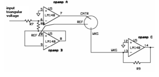
<p>A three-electrode setup is required to perform cyclic voltammetry. The electrical current passes between the working and counter electrodes - and the potential difference between the third electrode and counter electrode is controlled. This setup allows us to take voltage and current readings that do not interfere with each other.</p> | <p>A three-electrode setup is required to perform cyclic voltammetry. The electrical current passes between the working and counter electrodes - and the potential difference between the third electrode and counter electrode is controlled. This setup allows us to take voltage and current readings that do not interfere with each other.</p> | ||
| - | </html>[[image:Calgary2011_potentiostat.png|thumb|400px|center|<b>Figure | + | </html>[[image:Calgary2011_potentiostat.png|thumb|400px|center|<b>Figure 3</b> A schematic for a potentiostat suitable for performing cyclic voltammetry. Source: Gopinath and Russell, 2005.]]<html> |
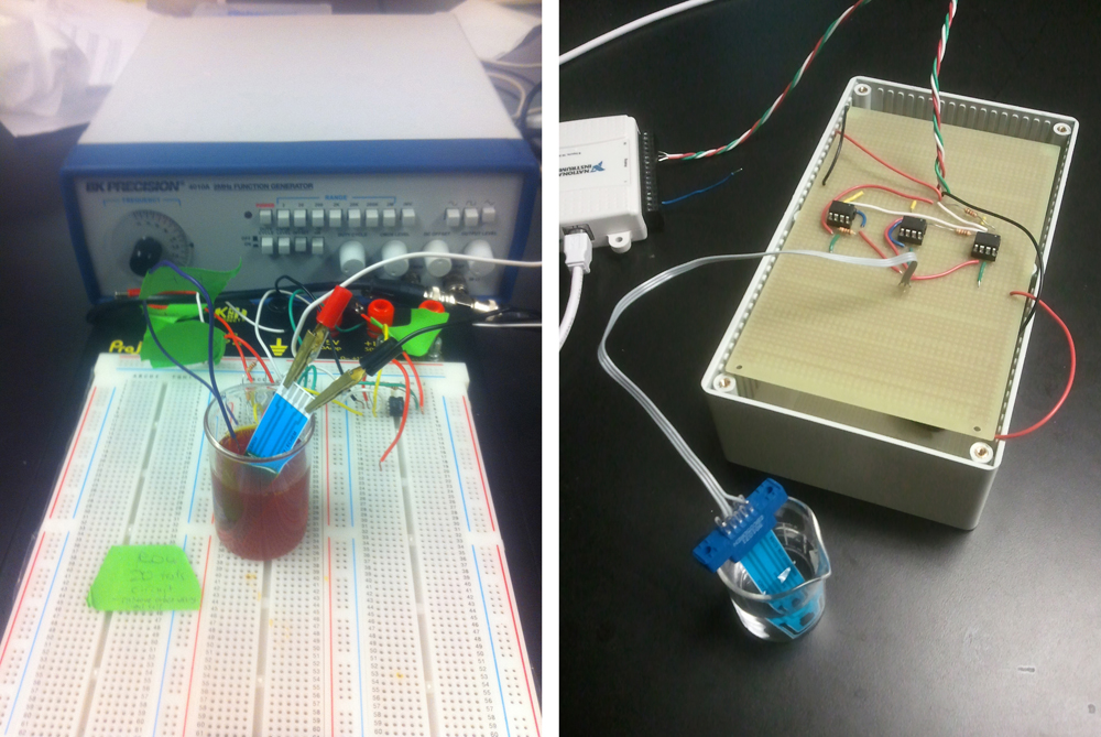
<p>In order to perform cyclic voltammetry, specialized equipment is usually required. Because such equipment is usually unavailable in biology labs, we built our own potentiostat - a piece of equipment that outputs a known voltage and measures a corresponding current across two electrodes. Although we used a commercially available potentiostat to conduct our experiments, we decided to build our own to demonstrate that a cheap, reliable set-up is feasible.</p> | <p>In order to perform cyclic voltammetry, specialized equipment is usually required. Because such equipment is usually unavailable in biology labs, we built our own potentiostat - a piece of equipment that outputs a known voltage and measures a corresponding current across two electrodes. Although we used a commercially available potentiostat to conduct our experiments, we decided to build our own to demonstrate that a cheap, reliable set-up is feasible.</p> | ||
| - | </html>[[image:Calgary2011_ourpotentiostat.jpg|thumb|200px|center|<b>Figure | + | </html>[[image:Calgary2011_ourpotentiostat.jpg|thumb|200px|center|<b>Figure 4</b> A potentiostat setup capable of taking cyclic voltammetry measurements.]]<html> |
For preliminary data, <a href="https://2011.igem.org/Team:Calgary/Project/Preliminary_Data">click here</a>. | For preliminary data, <a href="https://2011.igem.org/Team:Calgary/Project/Preliminary_Data">click here</a>. | ||
Revision as of 23:08, 28 September 2011


Reporter

What is a Reporter?
It isn't enough to just be able to detect something - after the presence of naphthenic acids are confirmed by our promoter, we require some way for our bacteria to report back results that can be interpreted by an observer. Over the course of the project, Team Calgary considered three different reporter systems - colorimetric, fluorescent, and electrochemical.
Why Electrochemical?
Oilsands tailings ponds samples are difficult to work with for several different reasons. First of all, tailings ponds samples are murky, and can have greatly varying compositions from pond to pond. It would be difficult to obtain accurate colorimetric data from these samples, and it would be similarly difficult to readily observe fluorescence. Because an electrochemical response does not rely on being able to see anything, Team Calgary determined the electrochemical reporter to be ideal for this purpose.
Electrochemical reporters offer several advantages over visually-determined reporters. The signal is robust - environmental factors such as the presence of pollutants or sample turbidity do not affect the signal. Every molecule has a different oxidation potential - because we know the exact oxidation potential for our analyte, we can easily tell the difference between our desired signal and background noise. Another advantage of an electrochemical response is that the data is immediately available in digital form. This allows for fast graphical interpretation of the data as well as maximum information collection from the data.
A Novel Application for the lacZ Gene
We decided to use the lacZ gene in our electrochemical reporter. Traditionally, the lacZ gene is used as a reporter for blue-white screening. The gene product, ß-galactosidase, is an enzyme which is capable of cleaving various substrates. When x-gal is added for exmaple, ß-galactosidase cleaves it, producing a visible blue color. Recently however, Biran et al showed that ß-galactosidase can also cleave p-aminophenyl-ß-D-galactopyranoside (PAPG), producing p-aminophenol (PAP). PAP can be oxidized at an electrode and the signal converted into a current signal. It’s been shown that chlorophenolred-ß-D-galactopyranoside (CPRG) can also be cleaved by beta-galactosidase, producing chlorophenol red (CPR) and galactosidase. This produces a distinct color change (yellow to purple), and can also be oxidized at an electrode and converted into a current signal.Building our System
One of the main reasons we selected a electrochemical response for our system was that the response can be detected and processed digitally, without the need for qualitative observations. Because all molecules have a different oxidation potential, we can easily detect the presence or absence of an analyte with a known oxidation potential.
The voltammetric technique we used to detect chlorophenol red was cyclic voltammetry - the input voltage is shown below.
As voltage slowly increases and decreases, each species present in solution will undergo a redox reaction at its respective oxidation potential. Because we know the oxidation potential of our analyte, chlorophenol red, we can ignore any background noise or pollution using this method.
A three-electrode setup is required to perform cyclic voltammetry. The electrical current passes between the working and counter electrodes - and the potential difference between the third electrode and counter electrode is controlled. This setup allows us to take voltage and current readings that do not interfere with each other.
In order to perform cyclic voltammetry, specialized equipment is usually required. Because such equipment is usually unavailable in biology labs, we built our own potentiostat - a piece of equipment that outputs a known voltage and measures a corresponding current across two electrodes. Although we used a commercially available potentiostat to conduct our experiments, we decided to build our own to demonstrate that a cheap, reliable set-up is feasible.
For preliminary data, click here.For characterization data, click here.

 "
"


