Team:Paris Bettencourt/Experiments/T7 diffusion
From 2011.igem.org
| Line 65: | Line 65: | ||
|- | |- | ||
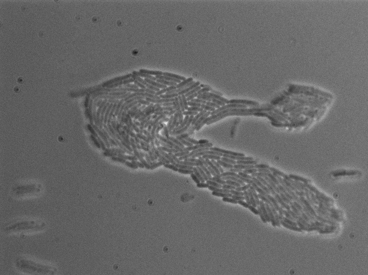
|[[File:T7 autoloop ctrl-31.jpg|450px|thumb|center|E.coli negative control at 37°C (trans image)]] | |[[File:T7 autoloop ctrl-31.jpg|450px|thumb|center|E.coli negative control at 37°C (trans image)]] | ||
| - | |[[File:T7 autoloop ctrl-33.jpg| | + | |[[File:T7 autoloop ctrl-33.jpg|450px|thumb|center|E.coli negative control at 37°C (rfp image)]] |
|} | |} | ||
| Line 75: | Line 75: | ||
|+T7 autoloop in E.coli at 37°C | |+T7 autoloop in E.coli at 37°C | ||
|- | |- | ||
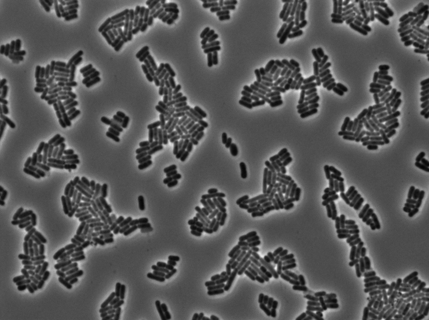
| - | |[[File:T7 autoloop ctrl-25.jpg| | + | |[[File:T7 autoloop ctrl-25.jpg|450px|thumb|center|E.coli T7 autoloop without terminator at 37°C (trans image)]] |
| - | |[[File:T7 autoloop ctrl-26.jpg| | + | |[[File:T7 autoloop ctrl-26.jpg|450px|thumb|center|E.coli T7 autoloop without terminator at 37°C (gfp image)]] |
|- | |- | ||
| - | |[[File:T7_loop_1.jpg| | + | |[[File:T7_loop_1.jpg|450px|thumb|center|E.coli T7 autoloop with terminator at 37°C (trans image)]] |
| - | |[[File:T7 loop 1 gfp.jpg| | + | |[[File:T7 loop 1 gfp.jpg|450px|thumb|center|E.coli T7 autoloop with terminator at 37°C (gfp image)]] |
|- | |- | ||
| - | |[[File:T7 autoloop ctrl-10.jpg| | + | |[[File:T7 autoloop ctrl-10.jpg|450px|thumb|center|E.coli negative control at 37°C (trans image)]] |
| - | |[[File:T7 autoloop ctrl-11.jpg| | + | |[[File:T7 autoloop ctrl-11.jpg|450px|thumb|center|E.coli negative control at 37°C (gfp image)]] |
|} | |} | ||
Revision as of 02:05, 22 September 2011

T7 diffusion experiments
Design overview
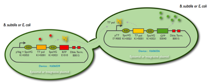
 Fig1: Schematic summary of the T7 diffusion device
More information on the design here : link
Parts
We synthetized the pHyperSpank promoter (K143055), but we were not able to incorporate it into our biggest construct. Instead, we cloned a Pveg promoter SpoVG(K143053) that has a constitutive expression.
The following schematic represents what we have indeed managed to clone:
This summary shows the parts we have characterized, and the ones we have sent to the registry. But for the moment, we didn't manage to clone them into an integration vector (K090403) nor a replicative vector (pHM3) for subtilis, as well as the combination of the emittor and the receiver inside the same plasmid.
Characterization of the T7 promoter
In order to characterize the pT7 promotor, we used the construct: pT7-RBS-GFP-T7ter. This construct was transformed into BL21 strains expressing the T7 polymerase under IPTG induction.Fluorescence kinetics
The measurements have been carried out on a spectrophotometer, at 37°C under transient shaking. The experiment lasted 4h, we tested several colonies and several IPTG concentrations. The OD 600nm and the fluorescence of the GFP (exc: 470nm / meas:515 nm) was measured every 5 min, and the ratio of the two was calculated.
All values were normalized by substracting the fluorescence/OD value of the well with 0 mM IPTG at time 0. The values given are in arbitrary units.
After 2 hrs of induction, we see a clear increase of the fluorescence proportional to the IPTG concentration (that is to say with the quantity of T7 polymerase induced in the cell). After 4 hrs, the expression of GFP under the pT7 is still not saturated
Here, we plot the ratio of induction of the T7 polymerase dependant construct for the different concentrations of IPTG at a given time (4 hrs), taking the well with 0 IPTG at time 0 as the reference.
Characterization of the T7 signal amplification leakage in E. coli
We characterized T7 autoloop in E.coli, when hosted in the plasmid pSB1C3 (K606036). The idea was to see if the system was leaky inside a synthetic biology plasmid, that is to say, a plasmid holding 4 terminators before any construct.
We found out there is a small leakage with the T7 emitter RFP. The cells in which RFP production is activated stop dividing and glow very strongly.
The first pictures show that the RFP construct is working efficiently since some cells are glowing with RFP fluorescence. This also shows the system is not as leaky as we expected. Indeed, the promoter regulating RFP expression is 'pVeg' which is a constitutive promoter. Finally, the RFP system is working very well because when leak occurs, cells glow very strongly.
These pictures show that the T7 GFP autoloop construct has been well done since some cells are glowing with GFP fluorescence contrary to the negative control.Thus, we can conclude that the T7 polymerase works. Finally, we notice there is no difference between the GFP autoloop with and without terminator this may be due to this terminator is B.subtilis terminator, moreover, we know that in this E.coli strain has 4 terminators.
Future
In order to get a better characterization of our systems and to tweak a wide range of parameters, we have already built a microfluidic device and are doing some preliminary experiments.
Afterwards, we want to clone the LacI expression system (<partinfo>BBa_K606054</partinfo>) into the emitter cell (<partinfo>BBa_K606039</partinfo>) in order to bring T7 under the control of LacI, and thus permit IPTG induction.
Finally, we plan to insert these BioBricks into a replicative vector, like pHM3, or an integrative vector, like <partinfo>BBa_K090403</partinfo>, for B.subtilis in order to test the communication and the transfer of T7 polymerase through the nanotubes.
 "
"


