Team:Calgary/Project/Reporter/Optimization
From 2011.igem.org
Rpgguardian (Talk | contribs) |
|||
| (2 intermediate revisions not shown) | |||
| Line 6: | Line 6: | ||
<h1>Introduction</h1> | <h1>Introduction</h1> | ||
| - | <p>For the electrochemical detection system to achieve | + | <p>For the electrochemical detection system to achieve its full potential, various conditions needed to be optimized for our purposes. These included the buffer solution present and the type of electrode plating used. The final conditions will be incorporated into the field-ready kit that can be used by anyone with minimal training.</p> |
<br><h1>Buffer Solutions</h1> | <br><h1>Buffer Solutions</h1> | ||
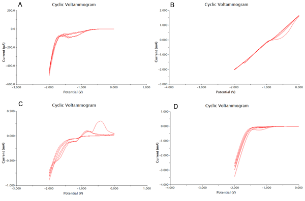
<p>We tested 11 potential buffering systems to find the optimal graph for chlorophenol red detection. The hallmark of a good buffer is one that can conduct a current effectively and has no species present that will undergo a redox reaction at the voltage you are measuring. For our project, we were looking at an oxidation reaction at -0.7V on our detection system. A good buffer for us will have a consistent flat line between -1V and -0.5V. Another feature of a good buffer is that the difference between the cathodic and anodic sweeps is not large. This is easy to notice, as the larger the difference, the bigger the gap between upper and lower lines during the flat section around 0V. The results of our buffer screens are shown in Figure 1 and Figure 2.</p></html> | <p>We tested 11 potential buffering systems to find the optimal graph for chlorophenol red detection. The hallmark of a good buffer is one that can conduct a current effectively and has no species present that will undergo a redox reaction at the voltage you are measuring. For our project, we were looking at an oxidation reaction at -0.7V on our detection system. A good buffer for us will have a consistent flat line between -1V and -0.5V. Another feature of a good buffer is that the difference between the cathodic and anodic sweeps is not large. This is easy to notice, as the larger the difference, the bigger the gap between upper and lower lines during the flat section around 0V. The results of our buffer screens are shown in Figure 1 and Figure 2.</p></html> | ||
| - | [[Image:Calgary2011 Voltammetry Table 1.png|thumb|center|400px|<b>Figure 1</b> Buffer solution testing. A is a control test of nanopure water. B is Tris-Cl pH7, C is TE pH8, D is 1x TAE, E is 1x PBS, F is KNO3 0.005M, G is KNO3 0.1M, and H is 0.01% acetonitrile]]<html></html> | + | [[Image:Calgary2011 Voltammetry Table 1.png|thumb|center|400px|<b>Figure 1.</b> Buffer solution testing. A is a control test of nanopure water. B is Tris-Cl pH7, C is TE pH8, D is 1x TAE, E is 1x PBS, F is KNO3 0.005M, G is KNO3 0.1M, and H is 0.01% acetonitrile]]<html></html> |
| - | [[Image:Calgary2011 Voltammetry Table 2.png|thumb|center|400px|<b>Figure 2</b> Buffer solution testing from only -2V to 0V to increase speed. A is 0.05M boric acid and 0.05M CaCl<sub>2</sub>, B is 0.1M CdSO<sub>4</sub>, C is 0.1M MgSO<sub>4</sub>, and C is 0.1M CaCl<sub>2</sub>]]<html> | + | [[Image:Calgary2011 Voltammetry Table 2.png|thumb|center|400px|<b>Figure 2.</b> Buffer solution testing from only -2V to 0V to increase speed. A is 0.05M boric acid and 0.05M CaCl<sub>2</sub>, B is 0.1M CdSO<sub>4</sub>, C is 0.1M MgSO<sub>4</sub>, and C is 0.1M CaCl<sub>2</sub>]]<html> |
| - | <p>Based on the results show above, 0.1M CaCl<sub>2</sub> was the best buffering system, as it had consistently flat areas through the testing range and conducted large currents. It was also shown that acetonitrile at 0.01% was the worst solvent, and it | + | <p>Based on the results show above, 0.1M CaCl<sub>2</sub> was the best buffering system, as it had consistently flat areas through the testing range and conducted large currents. It was also shown that acetonitrile at 0.01% was the worst solvent, and it caused massive electrode degradation during the test runs.</p> |
<br> | <br> | ||
<h1>Plating Methods</h1> | <h1>Plating Methods</h1> | ||
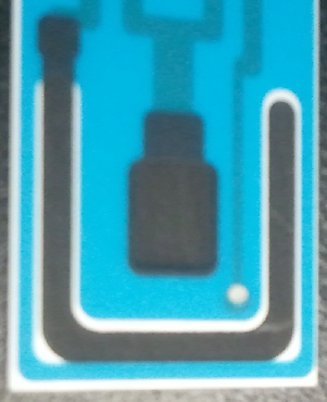
| - | <p>When an electrode is plated with a metal, the metal can participate in redox reactions to release or absorb electrons and conduct a current. This can enhance the resolution of an electrode and produce more easily interpretable results. One important example of plated electrodes is | + | <p>When an electrode is plated with a metal, the metal can participate in redox reactions to release or absorb electrons and conduct a current. This can enhance the resolution of an electrode and produce more easily interpretable results. One important example of plated electrodes is that found for silver/silver chloride electrodes. The silver atoms from the silver chloride can absorb an electron and become silver metal. Due to the nature of this reaction and that it is highly characterized, it can be used as a reference electrode, and is shown as a small silver disk on our electrodes.</p></html> |
| - | [[Image:Calgary2011_Electrode.png|thumb|center|200px|<b>Figure 3</b> A screen printed carbon electrode showing the Ag/AgCl reference electrode as a small silver disk.]] | + | [[Image:Calgary2011_Electrode.png|thumb|center|200px|<b>Figure 3.</b> A screen printed carbon electrode showing the Ag/AgCl reference electrode as a small silver disk.]] |
<html> | <html> | ||
<br> | <br> | ||
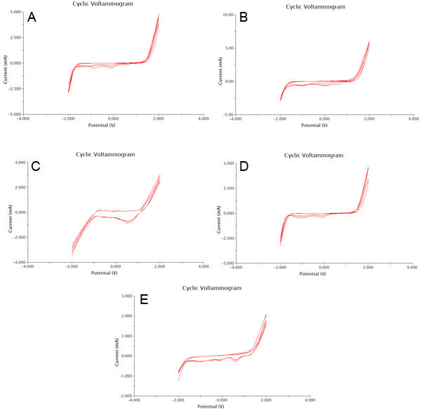
| - | <p>We tested a variety of common electroplating metals, including platinum, zinc, nickel, and copper. The results of our | + | <p>We tested a variety of common electroplating metals, including platinum, zinc, nickel, and copper. The results of our tests are shown below in Figure 4. From this data we concluded that nickel plating our electrodes was the best choice, and have included nickel in all of our electrochemistry procedures. This was chosen due to the decrease in size between the cathodic and anodic sweeps, as well as some decreased noise from extraneous species in the buffer. The only other plating method close to NiSO<sub>4</sub> was zinc thiocyanate, however this electroplating method had a peak that had higher overlap with the voltage range to be tested.</p> |
</html> | </html> | ||
| + | [[Image:Calgary2011 Voltammetry Table 3.png|thumb|center|400px|<b>Figure 4.</b> Tests of electroplating methods in a controlled environment. A is zinc thiocyanate, B is ZnSO<sub>4</sub>, C is chloroplatinic acid, D is NiSO<sub>4</sub>, and E is CuSO<sub>4</sub>.]] | ||
}} | }} | ||
Latest revision as of 03:29, 29 October 2011


Electrochemical Optimization

Introduction
For the electrochemical detection system to achieve its full potential, various conditions needed to be optimized for our purposes. These included the buffer solution present and the type of electrode plating used. The final conditions will be incorporated into the field-ready kit that can be used by anyone with minimal training.
Buffer Solutions
We tested 11 potential buffering systems to find the optimal graph for chlorophenol red detection. The hallmark of a good buffer is one that can conduct a current effectively and has no species present that will undergo a redox reaction at the voltage you are measuring. For our project, we were looking at an oxidation reaction at -0.7V on our detection system. A good buffer for us will have a consistent flat line between -1V and -0.5V. Another feature of a good buffer is that the difference between the cathodic and anodic sweeps is not large. This is easy to notice, as the larger the difference, the bigger the gap between upper and lower lines during the flat section around 0V. The results of our buffer screens are shown in Figure 1 and Figure 2.
Based on the results show above, 0.1M CaCl2 was the best buffering system, as it had consistently flat areas through the testing range and conducted large currents. It was also shown that acetonitrile at 0.01% was the worst solvent, and it caused massive electrode degradation during the test runs.
Plating Methods
When an electrode is plated with a metal, the metal can participate in redox reactions to release or absorb electrons and conduct a current. This can enhance the resolution of an electrode and produce more easily interpretable results. One important example of plated electrodes is that found for silver/silver chloride electrodes. The silver atoms from the silver chloride can absorb an electron and become silver metal. Due to the nature of this reaction and that it is highly characterized, it can be used as a reference electrode, and is shown as a small silver disk on our electrodes.
We tested a variety of common electroplating metals, including platinum, zinc, nickel, and copper. The results of our tests are shown below in Figure 4. From this data we concluded that nickel plating our electrodes was the best choice, and have included nickel in all of our electrochemistry procedures. This was chosen due to the decrease in size between the cathodic and anodic sweeps, as well as some decreased noise from extraneous species in the buffer. The only other plating method close to NiSO4 was zinc thiocyanate, however this electroplating method had a peak that had higher overlap with the voltage range to be tested.

 "
"


