Team:NYMU-Taipei/modelling-protein-structure-champ-design
From 2011.igem.org
Blackrabbit (Talk | contribs) (→B. Selection of a helical-pair structural motif based on sequence) |
(→How to Design the CHAMP Peptides) |
||
| (26 intermediate revisions not shown) | |||
| Line 3: | Line 3: | ||
| - | ==<font size=5><font color=crimson>What is the CHAMP Design</font>== | + | =='''<font size=5><font color=crimson>What is the CHAMP Design'''</font>== |
<font size=3> | <font size=3> | ||
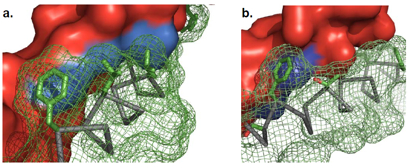
CHAMP, the computed helical anti-membrane protein, is designed by one of the computational and genetic methods available to engineer antibody-like molecules that target the water-soluble regions of tansmembrane (TM) proteins (Hang Yin, et al., 2007). | CHAMP, the computed helical anti-membrane protein, is designed by one of the computational and genetic methods available to engineer antibody-like molecules that target the water-soluble regions of tansmembrane (TM) proteins (Hang Yin, et al., 2007). | ||
| - | [[Image: paperchamp_NYMU.png|frame|none|Fig. 1a: Close-up of the predicted tightly packed interface between designed peptides and target protein. The target protein is represented by a red surface with a blue “hot spot”. Fig. 1b: The CHAMP backbone is depicted in ribbon representation with key positions designated for computational design shown in green (Hang Yin, et al., 2007)]] | + | [[Image: paperchamp_NYMU.png|frame|center|none|Fig. 1a: Close-up of the predicted tightly packed interface between designed peptides and target protein. The target protein is represented by a red surface with a blue “hot spot”. Fig. 1b: The CHAMP backbone is depicted in ribbon representation with key positions designated for computational design shown in green (Hang Yin, et al., 2007)]] |
</font> | </font> | ||
| - | ==<font size=5><font color=crimson>Why We Use the CHAMP Design</font>== | + | =='''<font size=5><font color=crimson>Why We Use the CHAMP Design</font>'''== |
<font size=3> | <font size=3> | ||
| Line 21: | Line 21: | ||
</font> | </font> | ||
| - | ==<font size=5><font color=crimson>How to Design the CHAMP Peptides</font>== | + | =='''<font size=5><font color=crimson>How to Design the CHAMP Peptides</font>'''== |
<font size=3> | <font size=3> | ||
We followed the design protocols in the paper- '''''Supporting Online Material for Computational Design of Peptides That Target Transmembrane Helices''''' (Hang Yin, et al., 2007) and '''''Understanding Membrane Proteins. How to Design Inhibitors of Transmembrane Protein–Protein Interactions''''' (J.S. Slusky, et al., 2009). However, because of the limited resources, we made little adjustments by using different programs, such as TMhit (Lo A., et al., 2009), ProtMod (Godzik A., et al., 2011), YASARA (Krieger E., et al., 2011), VMD (Klaus Schulten., et al., 2011), ΔG prediction server v1.0 (Hessa, T., et al., 2007) to finalize our CHAMP design. The study by '''''Interaction and conformational dynamics of membrane-spanning protein helices''''' (D Langosch, et al., 2009) and '''''Helix-helix interaction patterns in membrane proteins''''' (D Langosch, et al., 2010) gave us more knowledge about protein-protein interactions in transmembrane domains, and helped us during the CHAMP designing process. | We followed the design protocols in the paper- '''''Supporting Online Material for Computational Design of Peptides That Target Transmembrane Helices''''' (Hang Yin, et al., 2007) and '''''Understanding Membrane Proteins. How to Design Inhibitors of Transmembrane Protein–Protein Interactions''''' (J.S. Slusky, et al., 2009). However, because of the limited resources, we made little adjustments by using different programs, such as TMhit (Lo A., et al., 2009), ProtMod (Godzik A., et al., 2011), YASARA (Krieger E., et al., 2011), VMD (Klaus Schulten., et al., 2011), ΔG prediction server v1.0 (Hessa, T., et al., 2007) to finalize our CHAMP design. The study by '''''Interaction and conformational dynamics of membrane-spanning protein helices''''' (D Langosch, et al., 2009) and '''''Helix-helix interaction patterns in membrane proteins''''' (D Langosch, et al., 2010) gave us more knowledge about protein-protein interactions in transmembrane domains, and helped us during the CHAMP designing process. | ||
| - | + | <font size=4><font color=green>Membrane peptide design</font> | |
<font size=3> | <font size=3> | ||
| Line 39: | Line 39: | ||
<font size:3> | <font size:3> | ||
| - | [[Image: steps_NYMU.png|frame|none|Fig. 3:Design process for peptides that bind to transmembrane proteins. a. Superimposed helicalpair backbones of one structural motif. b. Selected backbone. c. Target structure is threaded onto one helix (front helix), positions for repacking are selected on the other helix. Repacked positions are highlighted in light gray with spheres on Cα. d. The designed helix (farther back) is repacked to have good van der Waals contacts with the target helix. Repacked positions shown in light gray with spheres on Cα. (Hang Yin, et al., 2007)]] | + | [[Image: steps_NYMU.png|frame|center|none|Fig. 3:Design process for peptides that bind to transmembrane proteins. a. Superimposed helicalpair backbones of one structural motif. b. Selected backbone. c. Target structure is threaded onto one helix (front helix), positions for repacking are selected on the other helix. Repacked positions are highlighted in light gray with spheres on Cα. d. The designed helix (farther back) is repacked to have good van der Waals contacts with the target helix. Repacked positions shown in light gray with spheres on Cα. (Hang Yin, et al., 2007)]] |
Our design based on these steps is shown in the following sections. | Our design based on these steps is shown in the following sections. | ||
</font> | </font> | ||
| - | + | <font size=4><font color=darkviolet>Section 1. Selection of a helical-pair structural motif based on sequence</font> | |
| - | + | <font size=3><font color=deeppink>A. Determining the domains of Mms13's amino acid sequence</font> | |
<font size=3> | <font size=3> | ||
| Line 60: | Line 60: | ||
'''Helix 1:a.a.12~29''' and '''Helix2:a.a.65~87'''. | '''Helix 1:a.a.12~29''' and '''Helix2:a.a.65~87'''. | ||
| - | [[Image: vote_NYMU.png|frame|none|Fig. 4: Part of result for cross-model majority vote]] | + | [[Image: vote_NYMU.png|frame|center|none|Fig. 4: Part of result for cross-model majority vote]] |
</font> | </font> | ||
| - | + | <font size=3><font color=deeppink>B. Selection of a helical-pair structural motif based on sequence</font> | |
<font size=3> | <font size=3> | ||
| - | <font color=mediumblue>We chose the TM helix which has a G-X3-G sequence motif.</font> The GxxxG motifs can induce the helices' interaction since it leads to the formation of a flat helix surface and can maximizes van der Waal’s interactions and that the loss of side-chain entropy upon association is minimal for Gly. (William P Russ, et al., 2000) Moreover, the Gly residues in the motifs reduce the distance between the helix axes facilitating hydrogen bond formation between the Cα-hydrogens and the backbone carbonyl of the partner helix (A. Senes, et al., 2001). After searching along the helices of Mms13, we found the critical G-X3-G sequence motifs on helix1 of the Mms13 (See Figure | + | <font color=mediumblue>We chose the TM helix which has a G-X3-G sequence motif.</font> The GxxxG motifs can induce the helices' interaction since it leads to the formation of a flat helix surface and can maximizes van der Waal’s interactions and that the loss of side-chain entropy upon association is minimal for Gly. (William P Russ, et al., 2000) Moreover, the Gly residues in the motifs reduce the distance between the helix axes facilitating hydrogen bond formation between the Cα-hydrogens and the backbone carbonyl of the partner helix (A. Senes, et al., 2001). After searching along the helices of Mms13, we found the critical G-X3-G sequence motifs on helix1 of the Mms13 (See Figure 5). |
| - | [[Image: mms13h1_NYMU.png|frame|Fig. | + | [[Image: mms13h1_NYMU.png|frame|Fig. 5: The critical G-X3-G motifs on helix1 of the Mms13]] |
</font> | </font> | ||
| - | + | <font size=4><font color=darkviolet>Section 2. Selection of a nativelike helical-pair backbone within the chosen structural motif</font> | |
<font size=3> | <font size=3> | ||
| - | After the selection of a helical-pair structural motif, we have to select a | + | After the selection of a helical-pair structural motif, we have to select a native-like helical-pair backbone as the templates for our CHAMP design. First, we follow the instructions to determine the template cluster. (R. F. S. Walters, et al., 2006) A library of 445 helical pairs from 31 proteins in the paper was clustered into groups based on their three-dimensional similarity. Different clusters have specific features and also show varying degrees of homogeneity. We finally choose cluster 2 as our candidates because of the antiparallel helices on Mms13 and the traits which belong to right-handed crossing angle on helix1. (For examples, the helix1 have small residues at the helix–helix interface, and they are also spaced at four-residue intervals.) The pie chart (See Figure 6) shows the fraction of the total number of pairs that fall within a given cluster and Table 1 (See Figure 7) shows some characteristics of the top 14 clusters. |
| - | After determining the cluster, we still have to choose one final template within 71 candidates | + | After determining the cluster, we still have to choose one final template from within the 71 candidates of cluster 2. We first eliminated the number of candidates to 27 templates through the prediction of van der Waals minimum distance of the helical pairs based on the uniformity of packing assessed by finding structures with the minimal number of inter-atomic contacts that are closer than 1.0 Å from the expected van der Waals minimum distance. (Hang Yin, et al., 2007) |
| - | Then to get the most matched template of our CHAMP design, we | + | Then to get the most matched template of our CHAMP design, we used the online program-TMhit (Lo A., et al., 2009) inferring helix-helix interactions from residue contact in Mms13. <font color=mediumblue>We selected the best template pairs by finding the template having one helix with the most residue contacts with Mms13 and whose sequence of another helix has the most residue alignments with Mms13.</font> After comparison, we chose protein '''1iwg: A437-A450 and A932-A945''' as the template pairs for our CHAMP design. Part of the data for the comparison is shown in Figure 8). |
| - | [[Image: | + | [[Image: cluster1_NYMU.png|frame|Fig. 7: Table1 with some characteristics of the clusters (R. F. S. Walters, et al., 2006)]] |
| - | [[Image: | + | [[Image: cluster_NYMU.png|frame|none|Fig. 6: The pie chart with the fraction of a given cluster (R. F. S. Walters, et al., 2006)]] |
| - | [[Image: excel_NYMU.png|frame|none|Fig. | + | <center>[[Image: excel_NYMU.png|frame|none|Fig. 8]]</center> |
</font> | </font> | ||
| - | + | <font size=4><font color=darkviolet>Section 3. Threading the sequence of the targeted TM helix onto the selected pair</font> | |
<font size=3> | <font size=3> | ||
| - | By using the online program-'''ProtMod-Protein Structure Modeling-Alignment''' (Godzik A., et al., 2011), we | + | By using the online program-'''ProtMod-Protein Structure Modeling-Alignment''' (Godzik A., et al., 2011), we got the pdb file of the repacking structure, where Mms13 is aligned onto the helix of the chosen template-'''1iwg: A437-A450'''. |
| - | [[Image: | + | [[Image: mms13b_NYMU.png|frame|Fig. 10a: The whole 1iwg protein. Figure 10b: The selected template pairs of 1iwg. Figures are graphed using YASARA View (Krieger E., et al., 2011)]] |
| - | [[Image: | + | [[Image: mms13a_NYMU.png|frame|none|Fig. 9: The aligned Mms13 structure from ProtMod (Godzik A., et al., 2011) graphed using YASARA View (Krieger E., et al., 2011).]] |
| - | After having both materials: the aligned Mms13 and the selected template pairs (1iwg: A437-A450; A932-A945), we threaded the Mms13 aligned sequence onto the corresponding helix. The threading process was finished by matching G-X3-G motif of Mms13 to the motif on the template structure. The backbones of the complex were then minimized to remove clashes with the threaded Mms13 sequence (See Figure | + | After having both materials: the aligned Mms13 and the selected template pairs (1iwg: A437-A450; A932-A945), we threaded the Mms13 aligned sequence onto the corresponding helix. The threading process was finished by matching G-X3-G motif of Mms13 to the motif on the template structure. The backbones of the complex were then minimized to remove clashes with the threaded Mms13 sequence (See Figure 11). |
| - | [[Image: | + | [[Image: dis_NYMU.png|frame|Fig. 12: The minimal inter-helical distances predicted by YASARA View (Krieger E., et al., 2011)]] |
| - | + | ||
| - | + | ||
</font> | </font> | ||
| - | + | [[Image: thread_NYMU.png|frame|none|Fig. 11]] | |
| + | |||
| + | |||
| + | <font size=4><font color=darkviolet>Section 4. Selection of the amino acid on CHAMP design with a side chain repacking algorithm</font> | ||
<font size=3> | <font size=3> | ||
| - | We gave a second stage repacking of the minimized structure and selected the one that showed a uniformly packed interior. We first found the proximal positions between Mms13 and the CHAMP template since the effect of the peripheral sequences are less dominant in the helical interaction. We used YASARA View (Krieger E., et al., 2011) to calculate the minimal inter-helical distances, VMD (Klaus Schulten., et al., 2011) to show the hydrophobic regions, and both to specify the proximal positions between helical pairs. The results are shown in Figures | + | We gave a second stage repacking of the minimized structure and selected the one that showed a uniformly packed interior. We first found the proximal positions between Mms13 and the CHAMP template since the effect of the peripheral sequences are less dominant in the helical interaction. We used YASARA View (Krieger E., et al., 2011) to calculate the minimal inter-helical distances, VMD (Klaus Schulten., et al., 2011) to show the hydrophobic regions, and both to specify the proximal positions between helical pairs. The results are shown in Figures 12 and 13. |
| - | [[Image: vmd_NYMU.png|frame|none|Fig. | + | [[Image: vmd_NYMU.png|frame|center|none|Fig. 13: The hydrophobic regions shown by VMD (Klaus Schulten., et al., 2011) indicate the peripheral regions since the membrane lipid bilayer is also non hydrophilic.]] |
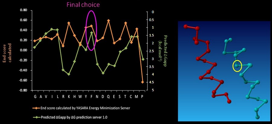
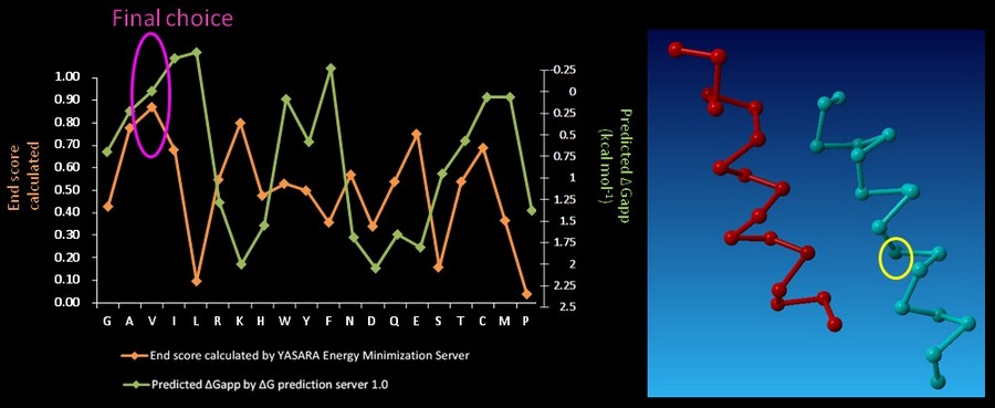
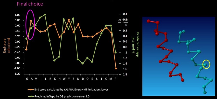
| - | On CHAMP anti-mms13 helix, seven proximal positions were selected for secondary repacking based on their proximity to the mms13-threaded helix. We used the '''YASARA Energy Minimization Server '''(Krieger E., et al., 2009) and the '''ΔG prediction server v1.0''' (Hessa, T., et al., 2007) to choose the residue sequences of proximal residues. We calculated the potentials following the potential energy functions (Hang Yin, et al., 2007) shown in Figure | + | On CHAMP anti-mms13 helix, seven proximal positions were selected for secondary repacking based on their proximity to the mms13-threaded helix. We used the '''YASARA Energy Minimization Server '''(Krieger E., et al., 2009) and the '''ΔG prediction server v1.0''' (Hessa, T., et al., 2007) to choose the residue sequences of proximal residues. We calculated the potentials following the potential energy functions (Hang Yin, et al., 2007) shown in Figure 14. |
| - | [[Image: function_NYMU.png|frame|Fig. | + | [[Image: function_NYMU.png|frame|Fig. 14: The Summations of the energy potential equation. (Hang Yin, et al., 2007)]] |
<font color=mediumblue>'''YASARA Energy Minimization Server''' (Krieger E., et al., 2009) is performed to calculate the '''EvdW + EHbond + Eelectrostatic + Econtact '''.</font> Though the program is based on predicting the potentials in the water, we can still rank the prefer residues by using the result scores as support for our decision. <font color=mediumblue>The other program, '''ΔG prediction server v1.0''' (Hessa, T., et al., 2007), in the other hand, we use it for computing the '''Esolvation + Eself''' potentials.</font> The results of '''ΔG prediction server v1.0''' (Hessa, T., et al., 2007) were ranked as well. By the cross-program comparison, we decided which residue is best for the corresponding proximal position. | <font color=mediumblue>'''YASARA Energy Minimization Server''' (Krieger E., et al., 2009) is performed to calculate the '''EvdW + EHbond + Eelectrostatic + Econtact '''.</font> Though the program is based on predicting the potentials in the water, we can still rank the prefer residues by using the result scores as support for our decision. <font color=mediumblue>The other program, '''ΔG prediction server v1.0''' (Hessa, T., et al., 2007), in the other hand, we use it for computing the '''Esolvation + Eself''' potentials.</font> The results of '''ΔG prediction server v1.0''' (Hessa, T., et al., 2007) were ranked as well. By the cross-program comparison, we decided which residue is best for the corresponding proximal position. | ||
| - | For each step of the energy calculation process, the identity of one of the proximal positions on the CHAMP helix was mutated. (Hang Yin, et al., 2007) By using the exhaustive enumeration and the cross-program ranking strategy, we determined whether the mutation is either accepted or rejected and set the best candidate residue for the corresponding proximal position. Only the rotamers with high probabilities of occurrence within helical backbones are considered. The data for energy calculation is showed in Figure | + | For each step of the energy calculation process, the identity of one of the proximal positions on the CHAMP helix was mutated. (Hang Yin, et al., 2007) By using the exhaustive enumeration and the cross-program ranking strategy, we determined whether the mutation is either accepted or rejected and set the best candidate residue for the corresponding proximal position. Only the rotamers with high probabilities of occurrence within helical backbones are considered. The data for energy calculation is showed in Figure 15 and 16. |
| + | |||
| + | [[Image: YASARA_NYMU.png|frame|center|none|Fig. 15: One example result of '''YASARA Energy Minimization Server''' (Krieger E., et al., 2009)]] | ||
| + | |||
| + | [[Image: gpre_NYMU.png|frame|center|none|Fig. 16: One example result of '''ΔG prediction server v1.0''' (Hessa, T., et al., 2007)]] | ||
| + | [[Image: multi1_NYMU.png|frame|center|none|Fig. 17: The second amino acid chosen by cross-ranking results.]] | ||
| + | |||
| + | [[Image: multi2_NYMU.png|frame|center|none|Fig. 18: The third amino acid chosen by cross-ranking results.]] | ||
| - | [[Image: | + | [[Image: multi3_NYMU.png|frame|center|none|Fig. 19: The sixth amino acid chosen by cross-ranking results.]] |
| - | [[Image: | + | [[Image: multi4_NYMU.png|frame|center|none|Fig. 20: The seventh amino acid chosen by cross-ranking results.]] |
| - | [[Image: | + | [[Image: multi5_NYMU.png|frame|center|none|Fig. 21: The tenth amino acid chosen by cross-ranking results.]] |
| - | [[Image: | + | [[Image: multi6_NYMU.png|frame|center|none|Fig. 22: The eleventh amino acid chosen by cross-ranking results.]] |
In the paper, when the identities of the proximal positions were determined, the membrane-exposed residues could then be fixed. <font color=mediumblue>The membrane-exposed positions are determined by random assignment of hydrophobic residues, with 60% probability given to Leu and 10% to Ala, Ile, Phe, and Val. (Hang Yin, et al., 2007)</font> Though it could be done by random selection, we still use '''ΔG prediction server v1.0''' (Hessa, T., et al., 2007) computing the energy to choose the CHAMP design with least energy. | In the paper, when the identities of the proximal positions were determined, the membrane-exposed residues could then be fixed. <font color=mediumblue>The membrane-exposed positions are determined by random assignment of hydrophobic residues, with 60% probability given to Leu and 10% to Ala, Ile, Phe, and Val. (Hang Yin, et al., 2007)</font> Though it could be done by random selection, we still use '''ΔG prediction server v1.0''' (Hessa, T., et al., 2007) computing the energy to choose the CHAMP design with least energy. | ||
| - | [[Image: exp_NYMU.png|frame|none|Fig. | + | [[Image: exp_NYMU.png|frame|center|none|Fig. 23: Results for choosing membrane-exposed positions.]] |
<font color=mediumblue>The main targeting sequences of the CHAMP peptide was finally set, the last step was adding the solubilizing groups at the N- and C-termini to insert the CHAMP into the lipid membrane.</font> We added both Lys residues to the termini of our CHAMP design. (Lys or polyethylene glycol-containing amino acids are used in the paper since the amino acids with positive charge can be driven by the negative charge of the lipid bilayer) (Hang Yin, et al., 2007). Our CHAMP design was then completed. | <font color=mediumblue>The main targeting sequences of the CHAMP peptide was finally set, the last step was adding the solubilizing groups at the N- and C-termini to insert the CHAMP into the lipid membrane.</font> We added both Lys residues to the termini of our CHAMP design. (Lys or polyethylene glycol-containing amino acids are used in the paper since the amino acids with positive charge can be driven by the negative charge of the lipid bilayer) (Hang Yin, et al., 2007). Our CHAMP design was then completed. | ||
</font> | </font> | ||
| - | ==<font size=5><font color=crimson>References</font>== | + | =='''<font size=5><font color=crimson>References</font>'''== |
<font size=3> | <font size=3> | ||
Latest revision as of 00:21, 29 October 2011

Contents |
What is the CHAMP Design
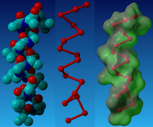
CHAMP, the computed helical anti-membrane protein, is designed by one of the computational and genetic methods available to engineer antibody-like molecules that target the water-soluble regions of tansmembrane (TM) proteins (Hang Yin, et al., 2007).
Why We Use the CHAMP Design
The general purpose of CHAMP design is that though Transmembrane (TM) helices usually play essential roles in biological processes, companion methods to target the TM regions are lacking. The CHAMP design of TM helices that specifically recognize membrane proteins would advance the understanding of sequence-specific recognition in membranes and simultaneously would provide new approaches to modulate protein-protein interactions in membranes (Hang Yin, et al., 2007).
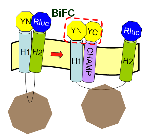
Now we want to let the CHAMP design play a pivotal role in our project to modulate the protein-protein interactions in membranes. But why is the CHAMP design so important in our iGEM project this year? In this year's Optomagnetic design, we want to use the designed peptide, CHAMP sequence, to inhibit the tight interaction between the two helices of membrane protein Mms13. Then we can successfully use mechanical force to change the conformation of Mms13 to induce the BiFC-based BRET phenomenon. If we do not have the target peptides, CHAMP, the two helices of Mms13 would tightly "stick" together and we can predict the results easily by the fundamental knowledge of physics that the magnetic force applied to the bacteria would not make any change to the conformation of Mms13 protein. If the two helices of Mms13 have tight interaction all the time, the wobbling light we expect in our project derived from BiFC-based BRET would not be excited. As the consequence of lacking the modulation of CHAMP, we would not get our final wobbling fluorescence but the constant light derived from a luciferase reaction; which means that we can only “turn on” neurons with constant light while the wobbling system can excite or inhibit the neurons for both “on and off” functions.
How to Design the CHAMP Peptides
We followed the design protocols in the paper- Supporting Online Material for Computational Design of Peptides That Target Transmembrane Helices (Hang Yin, et al., 2007) and Understanding Membrane Proteins. How to Design Inhibitors of Transmembrane Protein–Protein Interactions (J.S. Slusky, et al., 2009). However, because of the limited resources, we made little adjustments by using different programs, such as TMhit (Lo A., et al., 2009), ProtMod (Godzik A., et al., 2011), YASARA (Krieger E., et al., 2011), VMD (Klaus Schulten., et al., 2011), ΔG prediction server v1.0 (Hessa, T., et al., 2007) to finalize our CHAMP design. The study by Interaction and conformational dynamics of membrane-spanning protein helices (D Langosch, et al., 2009) and Helix-helix interaction patterns in membrane proteins (D Langosch, et al., 2010) gave us more knowledge about protein-protein interactions in transmembrane domains, and helped us during the CHAMP designing process.
Membrane peptide design
Transmembrane helical peptides can bind to targets with high specificity and affinity has been designed de novo (Hang Yin, et al., 2007). The method consists of four steps:
- Selection of a helical-pair structural motif based on sequence;
- Selection of a nativelike helical-pair backbone within the chosen structural motif;
- Threading the sequence of the targeted TM helix onto one of the two helices of the selected pair;
- Selection of the amino acid sequence of the designed peptide helix with a side chain repacking algorithm.
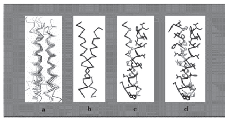
Our design based on these steps is shown in the following sections.
Section 1. Selection of a helical-pair structural motif based on sequence
A. Determining the domains of Mms13's amino acid sequence
The full sequence of Mms13 is (A.A.)
MPFHLAPYLAKSVPGVGVLGALVGGAAALAKNVRLLKEKRITNTEAAIDTGKETVGAGLATALSAVAATAVGGGLVVSLGTALVAGVAAKYAWDRGVDLVEKELNRGKAANGASDEDILRDELA.
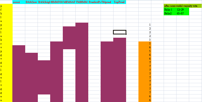
Because Mms13's structure is not 100% defined and known. We used several online prediction programs to specify the domains of Mms13 using amino acid sequences. We used sosui (Mitaku S., et al., 2002), DAS(low cut-off) (M. Cserzo, et al., 1997), DAS(high cut-off) (M. Cserzo, et al., 1997), TMHMM (Krogh A., et al., 2001), PredictProtein (Laszlo Kajan, et al., 2011), TMpred (K. Hofmann, et al., 1993), HMMTOP (G.E Tusnády, et al., 2001), MEMSAT-SVM (Nugent, T., et al., 2009), TopPred (Gunnar von Heijne, 1992). We then merged all the results using the cross-model majority vote to determine the boundaries of the two helices of Mms13.
Helix 1:a.a.12~29 and Helix2:a.a.65~87.
B. Selection of a helical-pair structural motif based on sequence
We chose the TM helix which has a G-X3-G sequence motif. The GxxxG motifs can induce the helices' interaction since it leads to the formation of a flat helix surface and can maximizes van der Waal’s interactions and that the loss of side-chain entropy upon association is minimal for Gly. (William P Russ, et al., 2000) Moreover, the Gly residues in the motifs reduce the distance between the helix axes facilitating hydrogen bond formation between the Cα-hydrogens and the backbone carbonyl of the partner helix (A. Senes, et al., 2001). After searching along the helices of Mms13, we found the critical G-X3-G sequence motifs on helix1 of the Mms13 (See Figure 5).
Section 2. Selection of a nativelike helical-pair backbone within the chosen structural motif
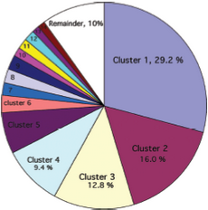
After the selection of a helical-pair structural motif, we have to select a native-like helical-pair backbone as the templates for our CHAMP design. First, we follow the instructions to determine the template cluster. (R. F. S. Walters, et al., 2006) A library of 445 helical pairs from 31 proteins in the paper was clustered into groups based on their three-dimensional similarity. Different clusters have specific features and also show varying degrees of homogeneity. We finally choose cluster 2 as our candidates because of the antiparallel helices on Mms13 and the traits which belong to right-handed crossing angle on helix1. (For examples, the helix1 have small residues at the helix–helix interface, and they are also spaced at four-residue intervals.) The pie chart (See Figure 6) shows the fraction of the total number of pairs that fall within a given cluster and Table 1 (See Figure 7) shows some characteristics of the top 14 clusters.
After determining the cluster, we still have to choose one final template from within the 71 candidates of cluster 2. We first eliminated the number of candidates to 27 templates through the prediction of van der Waals minimum distance of the helical pairs based on the uniformity of packing assessed by finding structures with the minimal number of inter-atomic contacts that are closer than 1.0 Å from the expected van der Waals minimum distance. (Hang Yin, et al., 2007)
Then to get the most matched template of our CHAMP design, we used the online program-TMhit (Lo A., et al., 2009) inferring helix-helix interactions from residue contact in Mms13. We selected the best template pairs by finding the template having one helix with the most residue contacts with Mms13 and whose sequence of another helix has the most residue alignments with Mms13. After comparison, we chose protein 1iwg: A437-A450 and A932-A945 as the template pairs for our CHAMP design. Part of the data for the comparison is shown in Figure 8).
Section 3. Threading the sequence of the targeted TM helix onto the selected pair
By using the online program-ProtMod-Protein Structure Modeling-Alignment (Godzik A., et al., 2011), we got the pdb file of the repacking structure, where Mms13 is aligned onto the helix of the chosen template-1iwg: A437-A450.
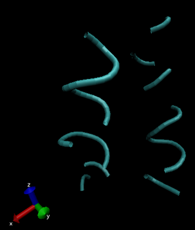
After having both materials: the aligned Mms13 and the selected template pairs (1iwg: A437-A450; A932-A945), we threaded the Mms13 aligned sequence onto the corresponding helix. The threading process was finished by matching G-X3-G motif of Mms13 to the motif on the template structure. The backbones of the complex were then minimized to remove clashes with the threaded Mms13 sequence (See Figure 11).
Section 4. Selection of the amino acid on CHAMP design with a side chain repacking algorithm
We gave a second stage repacking of the minimized structure and selected the one that showed a uniformly packed interior. We first found the proximal positions between Mms13 and the CHAMP template since the effect of the peripheral sequences are less dominant in the helical interaction. We used YASARA View (Krieger E., et al., 2011) to calculate the minimal inter-helical distances, VMD (Klaus Schulten., et al., 2011) to show the hydrophobic regions, and both to specify the proximal positions between helical pairs. The results are shown in Figures 12 and 13.
On CHAMP anti-mms13 helix, seven proximal positions were selected for secondary repacking based on their proximity to the mms13-threaded helix. We used the YASARA Energy Minimization Server (Krieger E., et al., 2009) and the ΔG prediction server v1.0 (Hessa, T., et al., 2007) to choose the residue sequences of proximal residues. We calculated the potentials following the potential energy functions (Hang Yin, et al., 2007) shown in Figure 14.
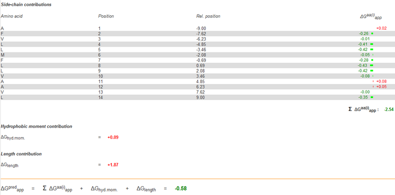
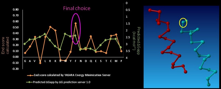
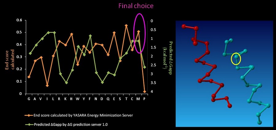
YASARA Energy Minimization Server (Krieger E., et al., 2009) is performed to calculate the EvdW + EHbond + Eelectrostatic + Econtact . Though the program is based on predicting the potentials in the water, we can still rank the prefer residues by using the result scores as support for our decision. The other program, ΔG prediction server v1.0 (Hessa, T., et al., 2007), in the other hand, we use it for computing the Esolvation + Eself potentials. The results of ΔG prediction server v1.0 (Hessa, T., et al., 2007) were ranked as well. By the cross-program comparison, we decided which residue is best for the corresponding proximal position.
For each step of the energy calculation process, the identity of one of the proximal positions on the CHAMP helix was mutated. (Hang Yin, et al., 2007) By using the exhaustive enumeration and the cross-program ranking strategy, we determined whether the mutation is either accepted or rejected and set the best candidate residue for the corresponding proximal position. Only the rotamers with high probabilities of occurrence within helical backbones are considered. The data for energy calculation is showed in Figure 15 and 16.
In the paper, when the identities of the proximal positions were determined, the membrane-exposed residues could then be fixed. The membrane-exposed positions are determined by random assignment of hydrophobic residues, with 60% probability given to Leu and 10% to Ala, Ile, Phe, and Val. (Hang Yin, et al., 2007) Though it could be done by random selection, we still use ΔG prediction server v1.0 (Hessa, T., et al., 2007) computing the energy to choose the CHAMP design with least energy.
The main targeting sequences of the CHAMP peptide was finally set, the last step was adding the solubilizing groups at the N- and C-termini to insert the CHAMP into the lipid membrane. We added both Lys residues to the termini of our CHAMP design. (Lys or polyethylene glycol-containing amino acids are used in the paper since the amino acids with positive charge can be driven by the negative charge of the lipid bilayer) (Hang Yin, et al., 2007). Our CHAMP design was then completed.
References
- Hang Yin, Joanna S. Slusky, Bryan W. Berger, Robin S. Walters, Gaston Vilaire, Rustem I. Litvinov, James D. Lear, Gregory A. Caputo, Joel S. Bennett, William F. DeGrado (2007). Supporting Online Material for Computational Design of Peptides That Target Transmembrane Helices. Science 315, 1817.
- J. S. Slusky, H. Yin and W. F. DeGrado (2009). Understanding Membrane Proteins. How to Design Inhibitors of Transmembrane Protein—Protein Interactions. PROTEIN ENGINEERING Nucleic Acids and Molecular Biology 22, 315-337.
- Lo A., Chiu Y.Y., Rødland E.A., Lyu P.C., Sung T.Y., and Hsu W.L. (2009) Predicting helix-helix interactions from residue contacts in membrane proteins. Bioinformatics 25, 996-1003.
- Lukasz Jaroszewski, Zhanwen Li, Xiao-hui Cai, Christoph Weber, and Adam Godzik. (2011) FFAS server: novel features and applications. Nucleic Acids Res. 39, W38–W44.
- Krieger E, Vriend G. (2002) Models@Home: distributed computing in bioinformatics using a screensaver based approach. Bioinformatics 18(2), 315-8.
- Krieger E, Koraimann G, Vriend G. (2002) Increasing the precision of comparative models with YASARA NOVA--a self-parameterizing force field. Proteins 47(3):393-402.
- Krieger E, Nabuurs SB, Vriend G. (2003) Homology modeling. Methods Biochem Anal.44:509-23.
- Krieger E, Joo K, Lee J, Lee J, Raman S, Thompson J, Tyka M, Baker D, Karplus K. (2009) Improving physical realism, stereochemistry, and side-chain accuracy in homology modeling: Four approaches that performed well in CASP8. Protein 77 Suppl 9:114-22.
- Venselaar H, Joosten RP, Vroling B, Baakman CA, Hekkelman ML, Krieger E, Vriend G. (2010) Homology modelling and spectroscopy, a never-ending love story. Eur Biophys J. 39(4):551-63.
- Joosten RP, te Beek TA, Krieger E, Hekkelman ML, Hooft RW, Schneider R, Sander C, Vriend G. (2011) A series of PDB related databases for everyday needs. Nucleic Acids Res. 39(Database issue):D411-9.
- William Humphrey, Andrew Dalke, and Klaus Schulten. (1996) VMD – Visual Molecular Dynamics. Journal of Molecular Graphics 14:33-38.
- R. Sharma, T. S. Huang, V. I. Pavlovic, K. Schulten, A. Dalke, J. Phillips, M. Zeller, W. Humphrey, Y. Zhao, Z. Lo, and S. Chu. (1996) Speech/gesture interface to a visual computing environment for molecular biologists. In Proceedings of 13th ICPR 96, volume 3, pp. 964-968.
- Rajeev Sharma, Michael Zeller, Vladimir I. Pavlovic, Thomas S. Huang, Zion Lo, Stephen Chu, Yunxin Zhao, James C. Phillips, and Klaus Schulten. (2000) Speech/gesture interface to a visual-computing environment. IEEE Computer Graphics and Applications 20:29-37.
- David J. Hardy, John E. Stone, and Klaus Schulten. Multilevel summation of electrostatic potentials using graphics processing units. Journal of Parallel Computing 35:164-177.
- Hessa, T., Meindl-Beinker, N., Bernsel, A., Kim, J., Sato, Y., Lerch, M., Lundin, C., Nilsson, I., White, SH. and von Heijne, G. (2007) Molecular code for transmembrane-helix recognition by the Sec61 translocon. Nature. 450, 1026-1030.
- Hessa, T., Kim, H., Lundin, C., Boekel, J., Andersson, H., Nilsson, I., White, SH. and von Heijne, G. (2005) Recognition of transmembrane helices by the endoplasmic reticulum translocon. Nature 433, 377-381.
- Dieter Langosch, Jana R. Herrmann, Stephanie Unterreitmeier and Angelika Fuchs. (2009) Structural Bioinformatics of Membrane Proteins- Helix-helix interaction patterns in membrane proteins.
- Dieter Langosch, Isaiah T. Arkin. (2009) Interaction and conformational dynamics of membrane-spanning protein helices. Protein Science 18: 1343–1358.
- Hirokawa T., Boon-Chieng S., and Mitaku S. (1998) SOSUI: classification and secondary structure prediction system for membrane proteins. Bioinformatics, 14:378-9.
- Mitaku S., Hirokawa T. (1999) Physicochemical factors for discriminating between soluble and membrane proteins: hydrophobicity of helical segments and protein length. Protein Eng. 11.
- Mitaku S., Hirokawa T., and Tsuji T. (2002) Amphiphilicity index of polar amino acids as an aid in the characterization of amino acid preference at membrane-water interfaces. Bioinformatics, 18:608-16.
- M. Cserzo, E. Wallin, I. Simon, G. von Heijne and A. (1997) Elofsson: Prediction of transmembrane alpha-helices in procariotic membrane proteins: the Dense Alignment Surface method. Prot. Eng. vol. 10, no. 6: 673-676.
- Krogh A, Larsson B, von Heijne G, Sonnhammer EL. (2001) Predicting transmembrane protein topology with a hidden Markov model: application to complete genomes. J Mol Biol. 305(3):567-80.
- Laszlo Kajan, Yachdav, G., Burkhard, R. (2011). High-throughput protein feature prediction in the cloud. Bioinformatics (submitted).
- K. Hofmann & W. Stoffel. (1993)TMbase - A database of membrane spanning proteins segments. Biol. Chem. Hoppe-Seyler:374,166.
- G.E Tusnády and I. Simon (2001) The HMMTOP transmembrane topology prediction server. Bioinformatics 17:849-850.
- Nugent, T. & Jones, D.T. (2009) Transmembrane protein topology prediction using support vector machines. BMC Bioinformatics. 10:159. Epub.
- Jones DT. (2007) Improving the accuracy of transmembrane protein topology prediction using evolutionary information. Bioinformatics. 23: 538-544.
- Jones DT, Taylor WR, Thornton JM. (1994) A Model Recognition Approach to the Prediction of All-Helical Membrane Protein Structure and Topology. Biochem. 33: 3038-3049.
- Gunnar von Heijne. (1992) Membrane Protein Structure Prediction, Hydrophobicity Analysis and the Positive-inside Rule. J. Mol. Biol. 225:487-494.
- William P Russ, Donald M Engelman. (2000) The GxxxG motif: A framework for transmembrane helix-helix association. Journal of Molecular Biology 296, Issue 3: 911-919
- Alessandro Senes, Iban Ubarretxena-Belandia, and Donald M. Engelman. (2001) The Cα—H⋅⋅⋅O hydrogen bond: A determinant of stability and specificity in transmembrane helix interactions. Proc Natl Acad Sci USA.31; 98(16): 9056–9061.
- R. F. S. Walters and W. F. DeGrado. (2006) Helix-packing motifs in membrane proteins. PNAS vol. 103 no. 37:13658-13663.
- Krieger E, Joo K, Lee J, Lee J, Raman S, Thompson J, Tyka M, Baker D, Karplus K Proteins. (2009) Improving physical realism, stereochemistry, and side-chain accuracy in homology modeling: Four approaches that performed well in CASP8. Proteins.77 Suppl 9:114-22.
 "
"


