|
|
| (40 intermediate revisions not shown) |
| Line 3: |
Line 3: |
| | <style type="text/css"> | | <style type="text/css"> |
| | | | |
| - | ul li a.currentlink3 { | + | ul li a.currentlinkdevice1 { |
| | color: black !important; | | color: black !important; |
| | } | | } |
| Line 11: |
Line 11: |
| | } | | } |
| | | | |
| - | ul li a.currentlinktop4 {
| |
| - | color: black !important;
| |
| - | display: block;
| |
| - | }
| |
| | | | |
| | </style> | | </style> |
| Line 24: |
Line 20: |
| | {{:Team:Wageningen_UR/Templates/Header}} | | {{:Team:Wageningen_UR/Templates/Header}} |
| | {{:Team:Wageningen_UR/Templates/NavigationTop1}} | | {{:Team:Wageningen_UR/Templates/NavigationTop1}} |
| - | == Customary fluidic device designed by Team Wageningen UR to measure oscillations == | + | == Custom fluidic device designed by Team Wageningen UR to measure oscillations == |
| | {{:Team:Wageningen_UR/Templates/NavigationLeftDevice}} | | {{:Team:Wageningen_UR/Templates/NavigationLeftDevice}} |
| | {{:Team:Wageningen_UR/Templates/Style | text= __NOTOC__ | | {{:Team:Wageningen_UR/Templates/Style | text= __NOTOC__ |
| Line 30: |
Line 26: |
| | ==== Design ==== | | ==== Design ==== |
| | | | |
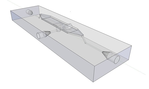
| - | The [http://www.nature.com/nature/journal/v463/n7279/abs/nature08753.html paper] our system is based on used microfluidic devices to measure oscillations. Such microfluidic devices however are very expensive and our iGEM team budget was limited, so we decided to design a customary fluidic device, which was produced in the Wageningen University workshop. To keep as many options as possible open, the design implemented the idea of potentially accommodating two bacteria growing platforms, a micro-sieve and a micro-dish. Gaining more in-depth understanding of our system, we decided to focus on the micro-dish as platform to test the oscillatory behaviour of our construct. Figure 1 and 2 below show the flow chamber as original scetch designed by our team and the 3D rendered depiction of the final device. | + | The article [1] we based our oscillatory system on, used microfluidic devices to physically constrain the host cells. This was necessary to induce and monitor oscillatory behavior of a population of ''E. coli''. Such microfluidic devices are very expensive and can only be used once. Therefore we set out to find a cheap alternative for these microfluidic devices. Because a proper alternative was not available we eventually designed our own flow device of which the design is seen in figure 1. For pictures of the device with dimensions click [https://2011.igem.org/Team:Wageningen_UR/Project/DevicesAdditional#Custom_fluidic_device_designed_by_Team_Wageningen_UR_to_measure_oscillations here] or download the Google sketch-up file [http://sourceforge.net/projects/theconstructor/files/ here]. |
| | | | |
| | | | |
| | + | [[File:mainpic.jpg|center]] |
| | | | |
| - | [[File:Scetch device WUR.jpg|400px]] [[File:Module-2 WUR.JPG|333px]]
| + | '''Fig.1:''' ''Wireframe model of designed flow device.'' |
| | | | |
| - | '''Fig.1:''' ''Design of the fluidic device: original scetch and 3D render''
| + | ===Bacterial growing platforms=== |
| | | | |
| | | | |
| - | The micro-dish contains porous wells, in which the cells can be physically constrained. It is placed in the socket of the dish, which allows a fluid to be flown over the wells. This fluid can be used to supply the cells with nutrients and wash away excess AHL and cells if necessary. Figure 2 shows a schematic of the device. The inflow and outflow1 can be used to flush the device with fresh medium. The use of outflow2 depends on the bacteria growing platform. In the case of the micro-sieve it can be used to create an under pressure, e.g. with a syringe, to trap the bacteria on the sieve. When using a micro-dish, it can optionally be used to bottom-feed the bacteria in the wells and/or supply additional substances to initalize the oscillatory behaviour of the system, e.g. IPTG in the case of the pRight/lacI hybrid promoter for the streamligned oscillator.
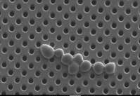
| + | This flow device can currently accommodate two bacterial growing platforms, a microsieve and a microdish. The microsieve - as depicted is figure 2 – consists of a carrier with membrane fragments. These membrame fragments contain evenly distributed pores of 200 nm in diameter. These membranes are used in the dairy industry to sterilize dairy products by removing micro-organisms through filtration. Through filtration a cake of cells will form on the membrane. This potentially gives us a platform capable of inducing and monitoring oscillatory behavior of a population of ''E. coli''. |
| | | | |
| - | [[File:Scheme_microsieve_WUR.png|center]] | + | [[File:microsieve.jpg|center]] |
| | | | |
| - | '''Fig.2:''' ''Schematic of the micro-fluidic device depicting the position of in- and outflow'' | + | '''Fig.2:''' ''Raster electron microscopy image of the microsieve with Saccharomyces cerevisiae cells.'' |
| | | | |
| | | | |
| - | [[File:Production_device_WUR.jpg|200px]]
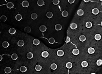
| + | Another bacterial platform is the microdish. The microdish – as depicted in figure 3 – is a thin acrylic layer with pores which is superimposed on a layer of porous aluminum oxide. The wells depicted in figure 3 have a diameter of 180 um and a depth of 40 um. Because the bottom of the wells is porous, nutrients can freely diffuse through the material to any cell contained in the well. These cells will divide until they are physically constrained by the borders of the well. Therefore this is another platform potentially capable of inducing and monitoring oscillatory behavior of a population of ''E. coli''. |
| - | '''Left:''' ''Production of the device in the Wageningen University workshop''
| + | |
| | | | |
| - | [[Team:Wageningen_UR/Project/Devices#Customary_fluidic_device_designed_by_Team_Wageningen_UR_to_measure_oscillations| back to top]]
| |
| | | | |
| | + | [[File:microdish.jpg|center]] |
| | | | |
| | | | |
| - | ==== Setup ====
| + | '''Fig.3:''' ''Light microscopy image of the microdish.'' |
| | | | |
| - | The main concern for the setup of the device was to be able to gain control over the flow rate. According to Bernoulli's principle, the velocity of a fluid can be influenced by varying the height of the medium bottle. This approach was also used in the paper cited above. Figure X. shows the corresponding setup and the applying equations.
| + | '''Implementation of both bacterial platforms in the design of the flow device.''' |
| | | | |
| - | [[File:Scheme_setup1_WUR.png|500px|left]] [[File:Setup1_WUR.JPG|200px|right]]
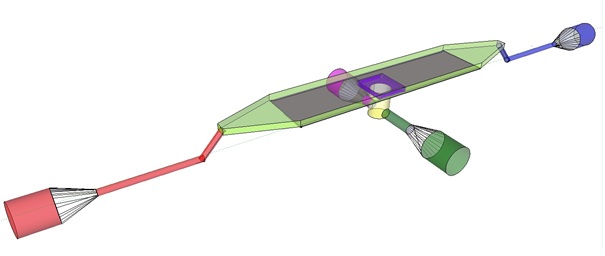
| + | The induction and observation of oscillatory behavior in a population of ''E. coli'' on the microsieve requires a cake of cells to be present on the membrane of the microsieve. In the dairy industry this is achieved by applying the filtrate through an inflow port leading to a chamber, which houses the microsieve. Because an overpressure is produced in the chamber, liquid will be forced through the sieve and the suspended particles – in our case ''E. coli'' cells – will aggregate on the sieve. To prevent that the pressure in the chamber becomes so high that cells get lysed by being pushed through the filter also an outflow port is included. In figure 4 the functional components of the flow device are depicted. |
| | | | |
| | | | |
| - | [[File:Equations_bernoulli_WUR.png]] | + | [[File:innerdevice.jpg|center]] |
| | | | |
| - | '''Fig.X:''' ''Setup of the device using Bernoulli's principle to control the velocity of the fluid.'' | + | '''Fig.4:''' Functional components of the flow device: In red the inflow port and channel to the top chamber of the flow device. In light green the flow chamber containing either in black the micro-dish or in purple the microsieve. In blue the outflow port of the top chamber. In yellow the bottom chamber with its respective in- and outflow channels and ports.'' |
| | | | |
| - | However, as mentioned on the [[Team:Wageningen_UR/Project/ModelingProj1#Conclusions_for_our_system| modeling page]], the dimensions of our fluidic device did not allow the aimed for precise control over the flow rate. This was tested both by calculating some theoretical values applicable for our device and running pilot experiments with water. Furthermore the obtained flow rates were also much faster than the flow rates in which oscillations were to be expected. This was solved by expanding our setup to incorporate the use of a syringe pump which controls the inflow. Figure X+1 shows the new setup.
| + | To induce and observe oscillatory behavior in a population of ''E. coli'' in the microdish, nutrients should be readily available for the cells located in the wells. To achieve this, the design - as depicted in figure 4 - implements a second set of inflow (in green) and outflow (in pink) ports. These ports connect to the lower chamber (yellow) and are used to flow a fresh supply of medium through the lower chamber. When the lower chamber is filled with medium, the medium can diffuse through the pores in the aluminum oxide hereby constantly giving the cells access to fresh medium. These ports connect to a chamber (yellow) come in contact with the aluminum oxide microdish (in black) when filled with medium. Through the addition of these ports a continuous supply of fresh medium is supplied. |
| | | | |
| - | [[File:Scheme_setup2_WUR.png|500px|center]]
| + | ===General design considerations.=== |
| | | | |
| - | '''Fig.X+1:''' ''Setup of the device using a pump to control the velocity of the fluid.''
| + | Because we want to use the flow device in combination with fluorescence microscopy the distance between the objective and the sample is crucial. Therefore we choose for a top chamber depth of 1 mm because in combination with the deckled of 1 mm, this distance is short enough for the focusing depth of the 20 x objective of the microscope. Furthermore this also reduces the volume of the chamber, reducing overhead liquid which could contain precious reactants, such as acyl-homoserine-lactone (AHL). |
| | | | |
| | | | |
| - | [[Team:Wageningen_UR/Project/Devices#Customary_fluidic_device_designed_by_Team_Wageningen_UR_to_measure_oscillations| back to top]]
| + | ===The Result.=== |
| | | | |
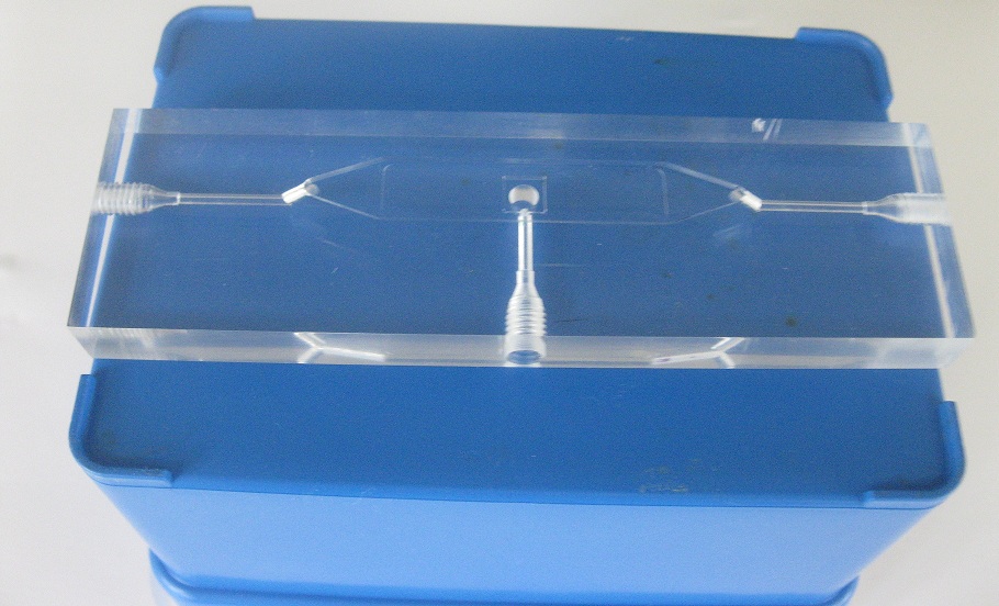
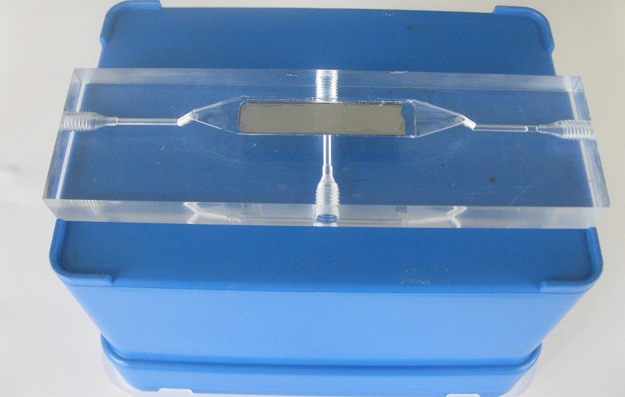
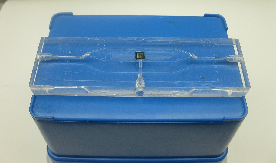
| | + | In the following pictures our flow device is depicted. In figure 5, the device is seen without any of the bacterial growing platforms installed. In figure 6, the flow device is seen with a microdish installed in the appropiate socket, depicted in black in figure 4. In figure 7, the flow device is seen with a microsieve installed in the appropiate socket, depicted in purple in figure 4. |
| | | | |
| - | ==== Measuring oscillations ====
| |
| | | | |
| - | [[File:Measuring_GFP_WUR.jpg|500px|center]] | + | [[File:without2.jpg|250px]] [[File:devicedish4.jpg|240px]] [[File:devicesieve2.jpg|260px]] |
| | + | '''Fig.4''' ''Flow device (left) with microdish (middle) and microsieve (right)'' |
| | | | |
| | | | |
| - | In order to be able to measure oscillations, the device was designed in such a way that it was possible to place it under a microscope. This would facilitate measuring GFP without having to use specialized additional equipment.
| |
| | | | |
| | + | [[Team:Wageningen_UR/Project/Devices#Design| back to top]] |
| | | | |
| - | [[File:Closeup_device_WUR.JPG|200px]][[File:Setup_WUR.jpg|500px|right]]
| |
| | | | |
| | + | '''Links and references:''' |
| | | | |
| - | '''Top:''' ''Devices under the microscope''
| + | [1][http://www.nature.com/nature/journal/v463/n7279/abs/nature08753.html Danino et al. 2010] |
| | | | |
| - | '''Right:''' ''Entire setup of the system''
| |
| | | | |
| | | | |
| | + | |
| | | | |
| | | | |
| Line 97: |
Line 94: |
| | | | |
| | | | |
| - | By chance an oscillatory behaviour of a transfomed ''E.coli'' containing the [[Team:Wageningen_UR/Project/CompleteProject1Description#Streamlined_Design| streamlined construct]] was observed in one of the experiments performed with a plate reader. This suggested oscillations could occur even without applying any flow over the wells. Letting the [[Team:Wageningen_UR/Project/ModelingProj1#Writing_a_modeling_tool_in_matlab| modeling tool]] iterate over a range of cell desities while keeping the flow rate constant at 0 confirmed that [[Team:Wageningen_UR/Project/ModelingProj1#Conclusions_for_our_system| oscillations could occur]] at high cell densities. Therefore the measurements for oscillatory behaviour of the construct were taken without applying any flow.
| |
| | | | |
| | | | |
| - |
| |
| - |
| |
| - |
| |
| - |
| |
| - |
| |
| - | [[Team:Wageningen_UR/Project/Devices#Customary_fluidic_device_designed_by_Team_Wageningen_UR_to_measure_oscillations| back to top]]
| |
| - |
| |
| - |
| |
| - | ==== Some fun facts about the device ====
| |
| - |
| |
| - |
| |
| - | *Getting the chambre watertight was a lot trickier than expected and many creative ideas came up:
| |
| - |
| |
| - |
| |
| - | [[File:Clamps_WUR.jpg|300px|center]]
| |
| - |
| |
| - |
| |
| - | *In the end silicone glue used for sealing aquariums solved the problem.
| |
| - |
| |
| - |
| |
| - | *The tubing and valves used for the final setup of the device were bought at a local pet store.
| |
| - |
| |
| - |
| |
| - | *During the first measurements, someone had to run to the microscope every ten minutes to take a picture. However, we built a LEGO robot controlling the microscope which could take the measurements and give our team lots of time to work on other interesting things.
| |
| - |
| |
| - |
| |
| - | [[File:robot_WUR.jpg|400px|center]]
| |
| - |
| |
| - |
| |
| - | [[File:mouse_WUR.jpg|300px|center]]
| |
| - |
| |
| - |
| |
| - | [[Team:Wageningen_UR/Project/Devices#Customary_fluidic_device_designed_by_Team_Wageningen_UR_to_measure_oscillations| back to top]]
| |
| | | | |
| | }} | | }} |
| - |
| |
| - |
| |
| - |
| |
| - |
| |
| - |
| |
| - | <!--
| |
| - | === Devices ===
| |
| - | =====Microfluidic devices=====
| |
| - | The platform best suited for these requirements is a microfluidic device, such as the one used by Danino & Hasty. However, such devices need to be custom designed and are prohibitively expensive. Because the design contains cell traps (ca. 100x50x2μm) the devices are difficult to clean, and it is likely that each device could be used only once. The underlying virtue of using a micro fluidic device is that it is a container that allows high enough cell densities for achieving threshold AHL levels while allowing cell density to remain constant independent of medium flow rate.
| |
| - | However, there exist a few alternatives that might fulfil the necessary requirements to serve as a platform for detecting oscillations. Some other alternatives besides the one already suggested, could be a standard microfluidic device (as opposed to a custom one) as offered by microliquid, these have a price around 150 euro’s a piece. This device consists of a linear channel which has an inflow and an outflow port. Danino & Hasty employed a similar design in his research of the propagation of the GFP signal. However, the dimensions of standard device are larger than the custom platform the micro-traps. Probably, this means that diffusion of the AHL will increase dramatically, slowing down oscillation periods. On the other hand, this device does not physically trap the cells the same way as the custom device. In this device the cells are trapped between the walls of the device locking them in place. These micro fluidic devices could be reusable.
| |
| - |
| |
| - | =====Small Chemostat=====
| |
| - | A second alternative might be a small chemostat. One of the benefits of using a chemostat is that it is continuously stirred, and thus AHL levels are the same throughout the culture. Therefore the system is not dependent on AHL diffusion. Due to the nature of a chemo-stat there is a continuous out-flow of cells, which might be problematic for reaching sufficient cell densities, and which can produce high enough levels of AHL. One way of solving this could be to use a system in which cells are retained in the system via the means of membranes. Another alternative might be at the molecular level, wildtype LuxR is activated when AHL concentrations reach ~100 nM. In the registry of standard biological parts a mutant LuxR(BBa_I729004) is available, which is activated at a concentration of 10nM. Thus this mutant LuxR can in theory reduce cell densities 10 fold, but still allow a functioning system.
| |
| - |
| |
| - | =====Microsieve=====
| |
| - | However, the most viable alternative to the microfluidic device might be a microsieve. This device also traps cells just like a microfluidic device. However the mechanism of entrapment is different: a microfluidic device traps cells in a physical trap, while microsieves do this by applying an overpressure. Through this overpressure cells are retained on the sieve. By varying the overpressure the thickness of the “cake” of cells can be varied. Furthermore these sieves are chemically inert and can withstand harsh chemical and physical circumstances, meaning that they can be cleaned and reused again.
| |
| - | The device consists of a microsieve contained in a flow chamber. The microsieve is made of silicon and contains pores as small as 200 nm. Because the sieve is made out of silicon it is chemically inert and can easily be cleaned and reused. The flow chamber has an inflow and two outflow ports. Through the inflow port a liquid enters containing suspended particles. When the liquid passes the micro sieve it will encounters negative pressure whereby particles are trapped by the sieve. As particles accumulated, they eventually form a “cake”. The filtered liquid leaves the device via the outflow port below the sieve, and remaining liquid in the chamber leaves the device via the outflow port 1.
| |
| - |
| |
| - |
| |
| - | [[File:mainproject09.png]]
| |
| - |
| |
| - | '''Fig.10.''' ''Schematic of a micro-filtration device. The microsieve is 5x5mm.''
| |
| - |
| |
| - |
| |
| - | [[File:mainproject10.png]]
| |
| - |
| |
| - | '''Fig.11.''' ''Photograph of cells growing on a microsieve.''
| |
| - |
| |
| - |
| |
| - | This device is particularly promising for a few reasons. Through the negative pressure a small pore size filter is able to be seeded with micro-organisms that will grow on its surface, as depicted in Figure 11. Once these micro-organisms are trapped and growth medium is supplied as inflow, they will start to divide and form a tight layer on the sieve.
| |
| - | Furthermore by adjusting the flow rate or filter pore size and porosity the cell layer can be varied of thickness. This could be necessary for reaching the correct balance between AHL production and removal. Another reason why this device is promising is because of its low price. The company Aqua Marijn, which is partly located at the departed of organic chemistry can produce custom versions of the chamber and supply the micro filter for around 50 euros per device. Preliminary discussions with representatives have proven to be promising. -->
| |
| - |
| |
| - |
| |
| - |
| |
| - |
| |
| - | <!--
| |
| - |
| |
| - | [[File:31.7_OD_0point143_blue.png]]
| |
| - |
| |
| - | '''Fig.2a.''' ''Pilot experiments with ptet_GFP: Directly after inoculation.''
| |
| - |
| |
| - |
| |
| - | [[File:31.7_OD_0point143_blue_after_1_hour.png]]
| |
| - |
| |
| - | '''Fig.2b.''' ''After 1 hour at a very low flow rate.'' -->
| |
 "
"


