Team:Harvard/Project/Synthesize
From 2011.igem.org
Overview | Design | Synthesize | Test | Zinc Finger Background | Protocols
Chip Synthesis
From Oligo Pool to Living Library
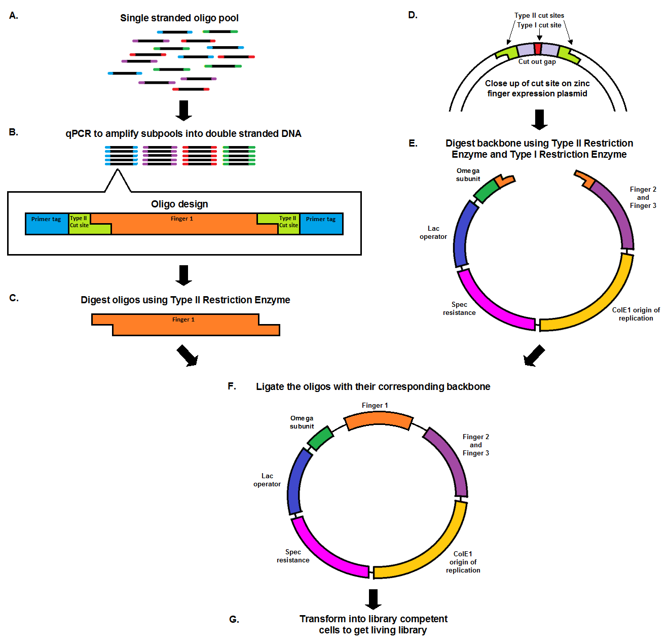
Chip synthesis results in a pool of single stranded oligos (A), designed with primer tags, which allow for the amplification of specific sub-pools, and Type II cut sites. qPCR, which amplifies the oligos at equal rates, results in the desired sub-pool (B). In order to prepare the oligo inserts and expression plasmid backbone for ligation, both must be cut with a Type II restriction enzyme (C, E). The cuts result in complementary sticky ends that anneal to each other during the ligation. The backbone, designed with a second cut site in the cut out gap (D), also undergoes a second digestion with a Type I restriction enzyme in order to minimize the number of undigested, or partially digested backbones. The oligo pool and backbone are then ligated (F), and transformed into library competent cells, resulting in a living library (G).
qPCR curves
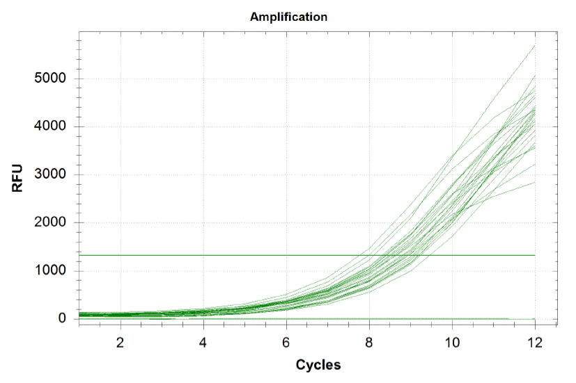
Each line on the graph below represents a qPCR for one of our sub-pools (each sequence we are targeting represents a sub-pool: CB top, CB bottom, FH top, FH bottom, Myc 198, Myc 981). By plotting the relative flouresence present in each cycle, we can visualize the pogress of the reaction. When performing a qPCR, one wants to run the reaction while the growth is still exponential. During this phase, all the oligos are replicated at equal rates. Once growth begins leveling off, as it does at the end of the graph below, the reaction should be stopped as the oligos are now being replicated unequally.
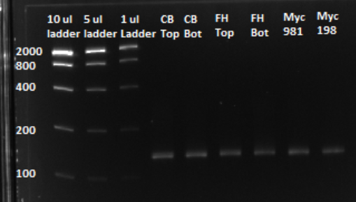
Based on the graph and gel below, we knew we successfully amplified each of our target sub-pools.
Because flourescence grows exponentially and just begins to level off at the end of the graph (where PCR was terminated), we are confident that overamplification did not occur, so individual oligos in each of our sub-pools were amplified at roughly equal rates. This preserves library integrity.
After a PCR clean up, we ran a gel in order to confirm that the qPCR produced the expected product, of approximately 130 bps. Based on the gel, we could conclude that our qPCR was indeed successful, and our oligo library was ready to use.
Zinc Finger Expression Plasmids
Once we had our 6 sub-pools of DNA, we needed to get that DNA into cells.
Expression Plasmid Schematic
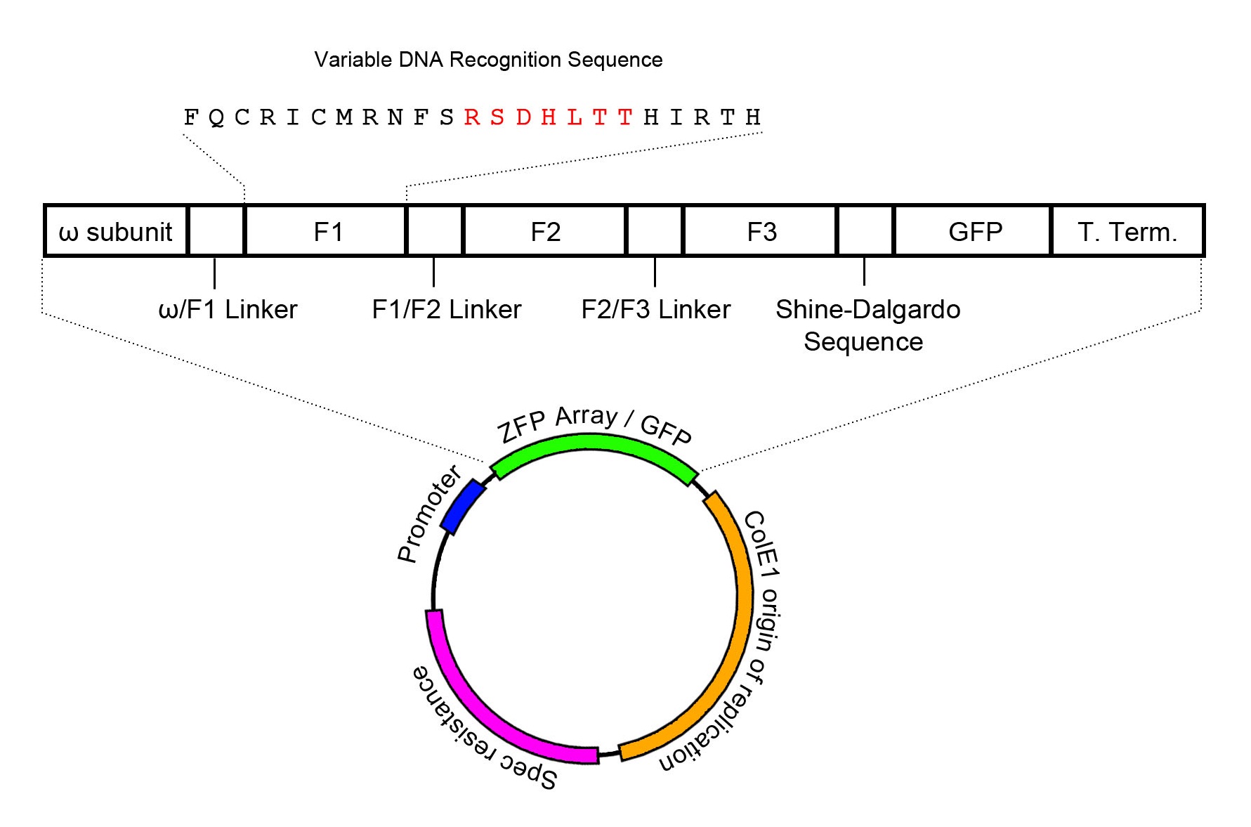
The zinc finger expression plasmid was assembled through two-piece Gibson assembly, and contains the ColE1 origin of replication in addition to a spectinomycin resistance cassette. The zinc finger array is conjugated to the omega subunit of RNA polymerase, providing the basis for a one-hybrid system such that zinc finger target binding recruits RNA polymerase to transcribe downstream genes. In order to visualize and confirm zinc finger expression, GFP has been added to the end of the mRNA transcript, and is translated through the Shine-Dalgarno sequence AGGAGG that prefaces GFP by 7 base pairs. However, it must be noted that this only confirms expression of zinc finger mRNA without confirmation on the protein level. Zinc finger expression is controlled through the lac operator. Intrinsic activation of the lac operator has been found to be sufficient to induce zinc finger expression in significant amounts.
The expression plasmid contains a spectinomycin resistance cassette alongside a ColE1 origin of replication. Expression of the zinc finger array is controlled by a lac operator. The zinc finger array is conjugated to the omega subunit of RNA polymerase, which will serve as a recruiter for polymerase when the zinc finger array binds to its target DNA recognition site.
It should also be noted that GFP is used as a reporter for zinc finger expression, and its expression is controlled through the use of a Shine-Dalgarno sequence to cause GFP to be expressed as a separate protein from the same mRNA transcript as the zinc finger array.
 "
"


