 "
"
Team:ENSPS-Strasbourg/Modeling
From 2011.igem.org
Introduction
The goal of our iGEM project is to create a software with a graphical user interface that allow a biologist to build models of small biological circuits and to start the associate simulation through a tool originally dedicated to the description and simulation of electronic circuits.
Nowadays, the design approach used in synthetic biology is similar to the one used in microelectronics. At mid-term, the design of a synthetic biology function is expected to be a kind of LEGO™ game which consists in assembling a set of elementary BioBricks. Similarly, over the past twenty years, the designing of complex electronic circuits, such as microprocessors, also consist in the assembly of standards cells picked-up in a design kit provider by silicon factories.
By this way, it is possible to design functional microelectronic systems compounds with more than 2 billion transistor (eg: Intel Xeon “Nehalem-EX”). This performance is possible thanks to the existence of powerful designing tools which are mostly semi-automatic. Today, the designing a digital electronic system require only an initial behavioral description of the targeted system and the ability to click on some buttons (in practice, design skill are still required in order to well configure the EDA (Electronic Design Automation) tool and to manually optimize some aspects of the design).
The power of EDA tools is their ability to carry out virtual testing, simulation, prediction and verification during the design process. Thus, the models of the standard cells are the keystone of this method. These are generally encoded in VHDL or VHDL-AMS languages which are “Hardware Description Languages” that are adapted to the need for EDA tools: VHDL models are understandable and usable by both the designer and the software.
In synthetic biology, the creation of Genetic Design Automation tools would be undoubltly an important vehicle for development of the field.
Our team comes from a project carried out during our studies at the Ecole Nationale Superieure de Physique de Strasbourg (E.N.S.P.S.). The project was co-directed by Professor Jacques HAIECH (Faculty of Pharmacy of Strasbourg, France) and Professor Christophe LALLEMENT (Institute of Solid State Electronics and Systems, Strasbourg, France). In both, they have set up a joint research team that works on this topic. Their philosophy is that one of the most serious runways for the mid-term development of a Genetic Design Automation tool requires an adaptation of the tools of microelectronics. Among the projects they lead, we intervened in the modeling of biological structures with electronic-dedicated languages.
As you will quickly realize the following, models, language and the tool used to encode models in electronics is not biologist-friendly, leading to the need off an interface allowing the biologist to first describe the system to simulate and then gather the simulation results.
Modeling
The goal of this page is to explain the way the VHDL and VHDL-AMS model are built. Although the development of the model was not directly an objective of the project, we had to understand how the models work in order to generate it. A first version of the model used in the following have already be published by our advisors [1]. However, to make them easy to be generated, their structures have been reviewed by our team.
VHDL or VHDL-AMS?
In the 80's, the digital circuits designers attempted to standardize the way to describe digital circuit. Until now, this was done with electronic schematics (with different symbols from one country to another), state diagram, sequential function chart … This universal description method they choose is a language, namely “hardware description language” (HDL). The first version, standardized by the IEEE in 1987, is the Very High Speed Integrated Circuit HDL. Today, only the ‘V’ of VHSIC remains. Quickly, VHDL was adopted by EDA tools (both for simulation and for synthesis).
In 1999, the dedicated IEEE standardization committee decided in 1999 to create an extension of VHDL to describe analog circuits and multi-domain (electro-thermal, for example) system. The VHDL-AMS language (AMS for Analog and Mixed Signal) was born. It aims at mid- term to replace the famous Spice simulator allowing the user to easily describe more complex behaviors.
Today, these two languages, as well as their brother in Verilog and Verilog-AMS are the keystones of the design flow.
How to describe how a BioBrick?
Up to now, we still do not really track how the language provided to describe electronic circuits could be used to describe biological systems. A first indication comes from [2]. It shows that the behavior of biological system may be modeled by an electronic circuit composed essentially with logic gates. Thus, a digital abstraction could be extracted for each BioBrick. This leads to the so-called behavioral model.
Another approach is to say that a BioBrick is a "transfer function" transforming biological signals to other biological signals. In this approach, each BioBrick is seen as a black box with input and outputs and differential equations to link output quantities to input quantities. The biological system is a diagram of such black boxes. At each simulation step, the quantities are computed step by step and the amount of species present in each cell is updated. This approach is called signal flow model.
The third approach lead to conservative model. This means that, potentially, each BioBrick may have an influence on each species present in the cell. This set of potential interaction can define, for each species, an interaction network leading to one differential equation by species. In practice, the differential equations of each species are coupled, giving a set of coupled equations to be solved at each simulation step.
How to describe behavioral models?
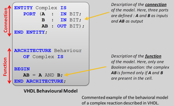
Behavioral models are the easiest to describe. It is based on VHDL language. In the cell, each protein can have only two states: “present” or “absent”. The chemical reactions or genetic processes that occur within the cell are modeled by logical functions:
• The mechanism of synthesis involving an activator A and repressor R and synthesizing the protein X can be modeled by the Boolean equation X = A AND NOT (R). This is the abstraction of Hill’s equation for which the Hill coefficients are infinite and the strength of the repressor is much larger than for the activator.
• The mechanism of complex reaction can be modeled by a Boolean AND function: the presence of the complex in the cell requires the presence of both reactants. It is an abstraction of a standard chemical differential equation for which kon is much larger than koff.
• If, in such a reaction, focus in put on a reactants (eg. A), another biological function (the inhibition) has to be defined. A "virtual protein" A’ is created at the output of this function giving the actual presence of reactant at the end of the reaction. The Boolean equation is A’ = A AND NOT (B), where B is the second reactant.
• In the case of two proteins A and B play an equivalent role for a given process, we introduce an OR gate and a virtual protein X = A OR B to connect to the targeted process.
In VHDL, the description of the digital blocks is quite simple. Below is the example for the complexation process.
Signal flow or conservative?
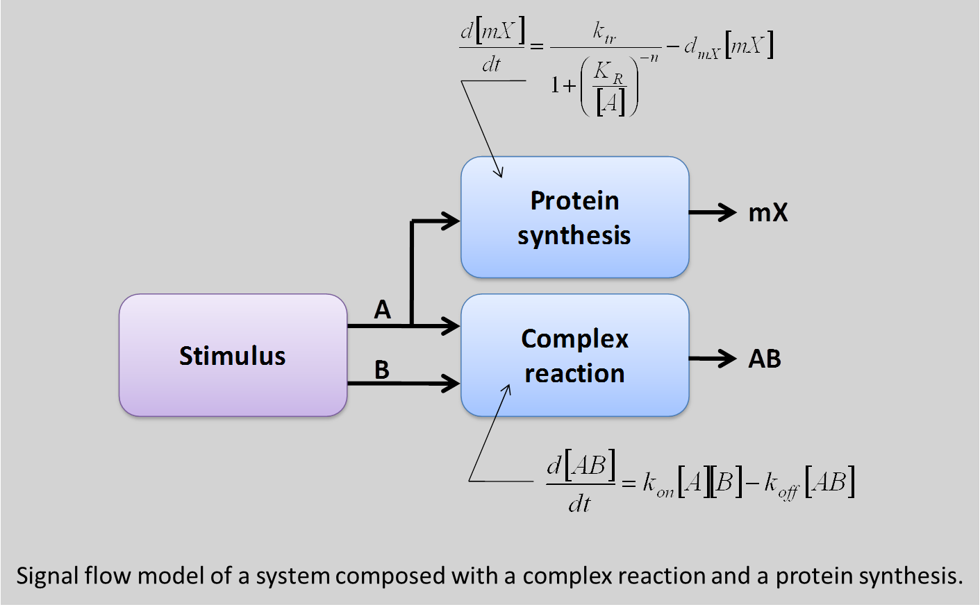
If the difference between the logic model and so-called analog models should be fairly well comprehensive, the difference between the conservative model and the signal flow model may be less. To illustrate this difference, consider a system composed with a complex reaction between two proteins A and B, and gene regulation mechanism where the protein A serves as a repressor (gene has a native promoter).
The signal flow model is composed to boxes: one modeling the complexation with two inputs (A and B) and an output [AB], and another one mode the gene repression with A as input and the expression of the gene G as output. To test the model, the input A and B of the system are connected to protein sources. With this signal flow model, the two blocks see the presence of an amount of A and, consequently, activates both mechanisms, leading to repression of the gene G.
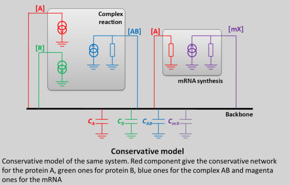
In the other hand, the conservative model defines a network for each species:
• For A: there is a mechanism of synthesis (the stimuli), a mechanism for consumption (the complex reaction) a storage mechanism by the cell and an auto-degradation.
• For B : the same network can be defined
• For AB, there is a mechanism of synthesis (the complex reaction) and an auto-degradation, which leads to an equilibrium.
• For mX, there is also a synthesis (gene expression corresponding to the mRNA synthesis) and an auto-degradation.
As a consequence, the amount of protein A can be calculated more accurately because all effects of the systems on A are taken into account. In particular, when B is present, if the complex reaction consumes more A than the stimuli synthesize, the amount of A in the cell is near to zero and the gene expression is not repressed.
This behavior cannot be describes by signal flow model. In fact, this case is very particular and, for the signal flow model, a “golden rule” was not respected. Indeed, a conservative system (as is biology) can be represented by a block diagram if and only if the influence of each block on its inputs is negligible. This is obviously not the case for a complex reaction.
With the conservative model allows, we can get rid of this rule and no assumptions are made about the behavior for blocks, which simplify strongly the modeling approach.
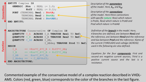
How to write a conservative model in VHDL-AMS?
Writing a conservative model with VHDL-AMS requires an experience of the language and a detailed understanding of VHDL-AMS mechanisms. This justifies the need to establish a dedicated tool to avoid the user having to write directly the VHDL-AMS code.
The conservative model of a system is constituted with two layers. One corresponds to the cell and the other one to the biological function under study. They share a common net, named backbone, on which each signal is connected.
The model of the cell is, in a first version, relatively easy. It consists in a set of capacitance, one par protein, modeling the storage ability of the cell. The model of the biological function is composed with a set of black boxes, one per biological mechanism. Each block box is composed with components which models, by their behavior, a biological process.
This analogy between biological process and electronic components lays on the fact that we consider that a flow of protein is equivalent to a flow of electrons. By extension:
• The integration of charges in a capacitance lead to a voltage or, in biology a concentration;
• A positive source of charge corresponds in biology to a synthesis process;
• A negative source of charge corresponds in biology to a protein consumption;
• A voltage source corresponds to a “biological thermostat” insuring a constant concentration in the cell.
• As it has been explained, a capacitance models the fact that the cell (or eventually a compartment of the cell) can accumulate proteins. In a general case, the value of capacitances in the model is set to 1.
• Finally, a resistance corresponds to phenomenon where the consumption of one species depends on its concentration. In biology, this phenomenon is the auto-degradation of proteins.
In a general case, voltage and current sources are not linear but commended by the concentration of the other species.
Using this analogy, the model of a biological function is an electrical network. However, there is a fundamental difference between the two models. In electronics, the electrons are the only information carrier and they cannot be distinguished from each other. In biology, the information carrier is the different protein which has to be distinguished.
VHDL-AMS allow integrating this aspect with the concept of NATURE. During the compilation of the model, VHDL-AMS create one conservative network by nature, which corresponds to our approach.
The example of VHDL-AMS model of the mRNA synthesis driven by an activator A and repressor R is shown below.
Which of the three models approach should implement?
In fact, all three because each has its own use.
The Electronic Design Automation (EDA) tools currently used in electronics can manipulate only digital objects. In this case behavioral model are required. It also permits a quick access to simulations that give a first idea about the behavior of the described systems.
The signal flow model is also very interesting. Compared with the digital model, it provides more precise information than the simple presence or absence of species in the cell. As the quantities are calculated step by step, the computation time remains affordable. However, it must be accepted that the simulation are completely accurate. In addition, a special care should be taken at the interface when a model is built.
Finally, the conservative model is the most accurate and closest to the actual behavior of organic bricks. It effectively takes into account the “load” effects of one block to the other. In addition, it benefits greatly from the fact that the VHDL-AMS simulations kernel is adapted for such a description, which is not the case with conventional tools. Its main drawback is the computing time. At every simulation step, a system of coupled ODE is solved. As a consequence, the simulation time increase exponentially with the complexity of the simulated system. In general, for a big system, conservative is used only locally to check precisely the behavior of a subsystem, or globally but only during the last stages of the design.
In our software, only the behavioral and the conservative descriptions are generated. The choice of the conservative model (in comparison with signal flow one) is motivated by the fact that, at present, the biological systems we describes remains simple and the critical size beyond which the model conservative model is penalizing by its computation time is not reached. In addition, due to “load” effect, conservative description files is easier to automatically generate that signal flow ones.
References
[1] Gendrault Y., Madec M., Lallement C., Pêcheux F., Haiech J., Synthetic biology methodology and model refinement based on microelectronic modeling tools and languages, Biotechnol. J. 6, pp. 796-806, 2011.
[2] R. Weiss, G. E. Homsy, T. F. Knight Jr., "Toward in vivo Digital Circuits", DIMACS Workshop on evolution as computation towards in vivo digital circuits, 1999.